Understanding Retroreflective Photoelectric Sensors
Retroreflective photoelectric sensors are widely used in industrial automation for detecting objects at a distance. They operate by emitting a light beam towards a reflector, which bounces the beam back to the receiver. When an object interrupts this beam, the sensor triggers a signal. These sensors are favored for their long sensing ranges and simplified alignment compared to through-beam types. However, their performance heavily relies on precise installation, where the mounting plate plays a critical role. A well-designed mounting plate ensures the sensor and reflector are correctly positioned, maintaining beam integrity and reducing false triggers. This guide delves into the specifics of selecting and installing mounting plates for optimal sensor functionality.
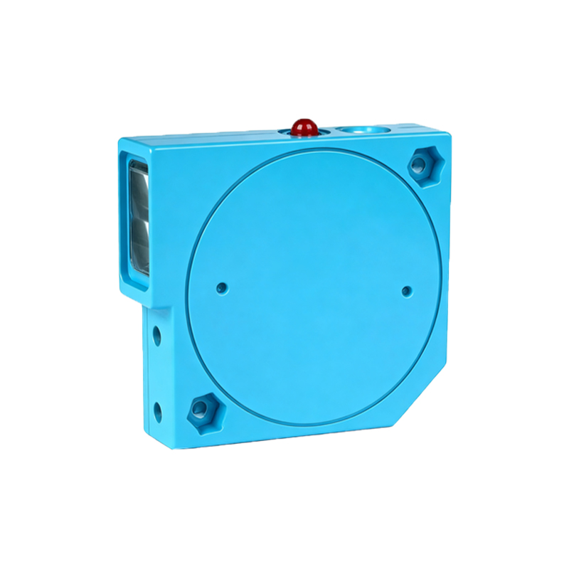
Key Components of a Mounting Plate
A mounting plate for a retroreflective sensor typically consists of a rigid base, adjustable brackets, and fastening mechanisms. The base is often made from durable materials like aluminum or stainless steel to withstand industrial environments, including vibrations and temperature fluctuations. Adjustable brackets allow for fine-tuning of the sensor's angle and height, ensuring the beam aligns perfectly with the reflector. Fastening mechanisms, such as bolts or clamps, secure the plate to machinery or frames. Additionally, some plates include slots or holes for cable management, preventing wire damage and interference. Understanding these components helps in choosing a plate that matches the sensor's specifications and application needs.
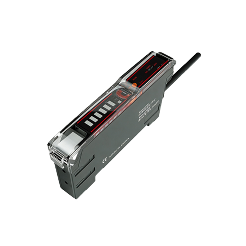
Installation Steps for Mounting Plates
Proper installation begins with selecting a stable surface free from obstructions. First, mount the plate using appropriate hardware, ensuring it is level and firmly attached. Next, secure the sensor to the plate, adjusting the brackets to point directly at the reflector. Use a alignment tool or the sensor's indicator lights to verify beam connection. Position the reflector opposite the sensor, making sure it is clean and unobstructed. Test the setup by passing an object through the beam, checking for consistent detection. Regularly inspect for misalignment due to environmental factors, and recalibrate as needed. Following these steps minimizes downtime and enhances sensor reliability.
Common Installation Challenges and Solutions
Installers often face issues like beam misalignment, environmental interference, and mechanical stress. Misalignment can occur from improper plate mounting or reflector placement, leading to failed detection. To address this, use plates with micro-adjustment features and conduct routine checks. Environmental factors such as dust, moisture, or bright ambient light may scatter the beam, causing false signals. Opt for sealed mounting plates and install protective shrouds. Mechanical stress from vibrations can loosen components over time; anti-vibration mounts and locking hardware help maintain stability. By anticipating these challenges, engineers can select robust mounting solutions that ensure long-term performance.
Maintenance and Best Practices
Regular maintenance of the mounting plate and sensor system is essential for sustained operation. Clean the plate and reflector surfaces periodically to remove debris that could block the beam. Inspect fasteners for tightness and brackets for wear, replacing any damaged parts promptly. Document alignment settings for quick recalibration after maintenance. Best practices include using manufacturer-recommended plates, training personnel on proper handling, and integrating the system with diagnostic tools for real-time monitoring. Adhering to these practices extends the lifespan of the sensor and reduces operational costs, making it a cost-effective investment for automation projects.