Understanding Collision Photoelectric Sensor Basics
Before initiating the wiring process, a fundamental understanding of collision photoelectric sensors is essential. These devices, often used in industrial automation for object detection and collision avoidance, operate by emitting a beam of light (typically infrared, visible red, or laser) and detecting its reflection or interruption. The core components include an emitter, a receiver, and a control circuit. The electrical interface is primarily defined by its output type, which is most commonly a solid-state transistor output—either NPN (sinking) or PNP (sourcing)—or a relay contact output. The sensor's datasheet is the ultimate authority for its specific voltage requirements, output configuration, and wiring diagrams. Misidentification of these parameters is a primary cause of system failure.
Essential Tools and Safety Precautions
Gather all necessary tools and materials prior to starting. You will typically need a screwdriver set, wire strippers, crimping tools, appropriate gauge electrical wires (often 18-22 AWG shielded cable is recommended for noise immunity), terminal blocks, and a DC power supply matching the sensor's voltage rating (commonly 12-24V DC). Safety is paramount. Always disconnect and lock out all power sources to the control panel and machinery. Verify the absence of voltage using a multimeter. Wear appropriate personal protective equipment (PPE) such as safety glasses and insulated gloves. Ensure the work area is clean, dry, and well-lit to prevent accidents and wiring errors.
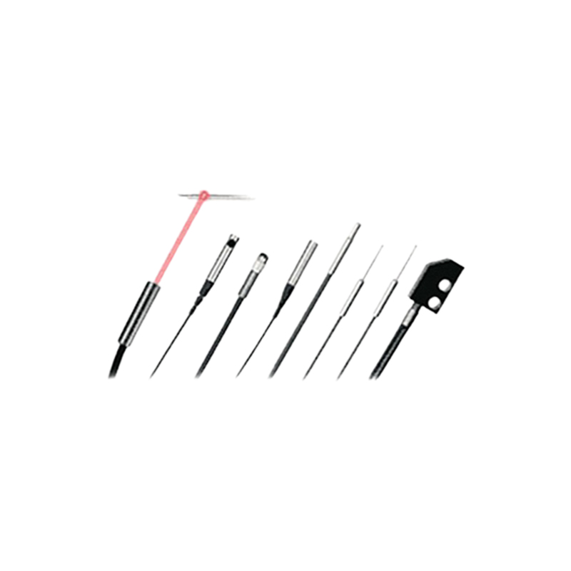
Interpreting the Sensor Datasheet and Wiring Diagram
The manufacturer's datasheet provides the critical roadmap for correct installation. Locate the wiring diagram, which is usually represented with simple symbols. Identify the following terminals: Supply Voltage Positive (V+ or Brown wire), Supply Voltage Negative (0V or Blue wire), Output Signal (Black or White wire), and sometimes a separate ground/shield terminal. For a standard 3-wire DC sensor, the configuration is consistent: Brown to V+, Blue to 0V, and Black to the load (e.g., a PLC input). Crucially, determine if the output is NPN or PNP. An NPN sensor sinks current to 0V when active, while a PNP sensor sources current from V+ when active. This dictates how it connects to your controller.
Step-by-Step Wiring Procedure for DC Sensors
Begin by preparing the cables. Strip a small portion of insulation from the end of each wire. If using ferrules, crimp them on for a secure connection in terminal blocks. First, connect the power supply. Route the positive lead from your DC power source to the sensor's V+ (brown) terminal. Connect the negative lead from the power source to the sensor's 0V (blue) terminal. Double-check polarity; reversing it can permanently damage the sensor. Next, connect the output. For a PNP sensor, the output wire (black) provides positive voltage when activated. Connect this wire to one side of your load (e.g., PLC input module). The other side of the load must then be connected back to the 0V of the power supply. For an NPN sensor, the output sinks to 0V. Connect the load between the V+ supply and the sensor's output wire.
Wiring Considerations for Noise and Interference
Industrial environments are electrically noisy. To ensure reliable sensor operation, implement noise reduction strategies. Always use shielded cable, with the drain wire or shield connected to a solid earth ground at the control panel end only. Avoid running sensor cables in parallel with high-voltage power lines or motor leads; cross them at a 90-degree angle if necessary. Keep cable runs as short as possible. For long runs or highly noisy environments, consider using twisted pair cables. If the sensor has a separate functional earth terminal, connect it to the grounding point. Proper grounding is not optional; it is critical for stabilizing the signal and protecting the circuitry from voltage spikes and electromagnetic interference (EMI).
Testing and Commissioning the Wired Sensor
After wiring is complete and visually inspected for tightness and correctness, proceed to testing. Re-energize the power supply. Most sensors have a status LED indicator. Observe its behavior. Typically, a steady or blinking green light indicates power and standby mode. Introduce a target object into the sensing field. The output LED (often yellow or orange) should illuminate, and the output state should change. Use a multimeter to verify the voltage at the output terminal relative to 0V. For a PNP sensor, you should read approximately the supply voltage when active. For an NPN, it should drop near 0V. Finally, integrate the signal with your PLC or controller and test the logic response in the control program to confirm the entire detection loop functions as intended.
Troubleshooting Common Wiring Issues
If the sensor fails to operate, follow a logical troubleshooting sequence. First, confirm power: Is the LED lit? Check voltage at the sensor terminals. Second, verify output activity: Does the output LED respond to the target? If not, check sensing alignment and range. If the LED responds but the controller does not, the wiring is likely at fault. For a PNP sensor connected to a PLC sinking input, the signal will not be read—a common mismatch. Ensure compatibility between sensor output type and controller input type. Check for loose connections, damaged wires, or incorrect polarity. Use the multimeter in continuity mode to check for broken circuits. Persistent issues may require consulting the datasheet for diagnostic modes or contacting technical support.