Introduction to Proximity Sensing Technology
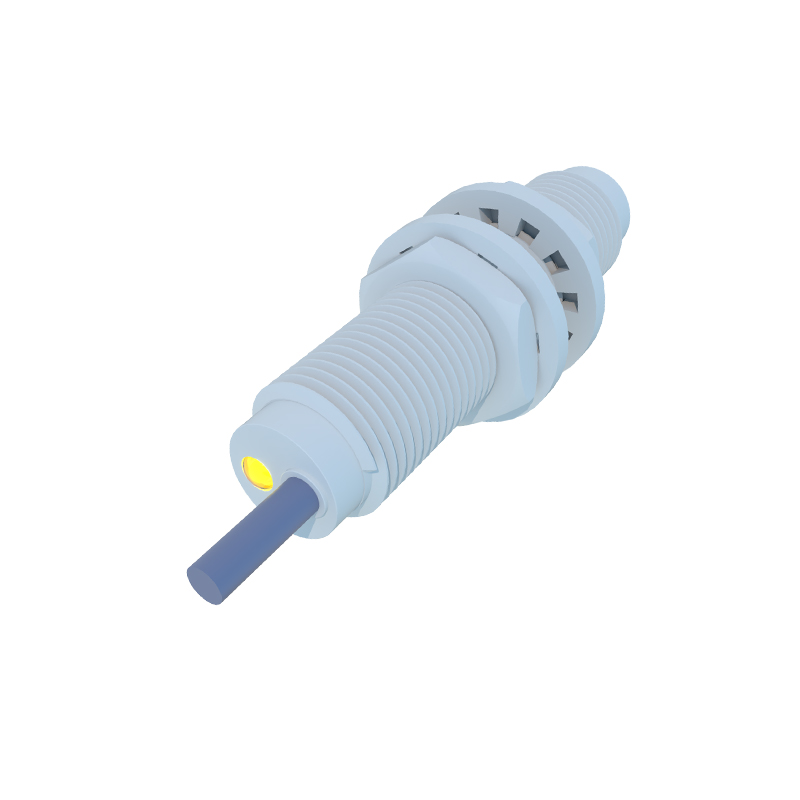
Proximity sensors are indispensable components in modern industrial automation, robotics, and consumer electronics. These devices detect the presence or absence of an object within a specified range without any physical contact. The core principle relies on changes in an electromagnetic field, capacitance, or light beam. As an electrical engineer, designing a robust and reliable proximity sensor circuit requires a deep understanding of the underlying physics, component selection, and noise immunity strategies. This guide delves into the practical aspects of circuit design for inductive and capacitive proximity sensors, which are among the most prevalent types in industrial applications. The design process encompasses oscillator circuits, signal conditioning, output stages, and essential protection mechanisms.
Inductive Proximity Sensor Core Circuit
The heart of an inductive proximity sensor is an LC oscillator circuit, typically a Colpitts or Hartley oscillator. This circuit generates a high-frequency electromagnetic field from a coil. When a metallic object enters this field, eddy currents are induced in the target, causing a power loss in the oscillator. This loss manifests as a reduction in the oscillation amplitude. The key design parameters include the frequency of oscillation (usually between 100 kHz and 1 MHz), the coil geometry (size, number of turns, core material), and the Q-factor. A higher Q-factor coil provides greater sensitivity but may also be more susceptible to environmental factors. Careful PCB layout is critical here; the oscillator components must be placed close to the sensing coil to minimize stray inductance and capacitance, which can destabilize the oscillation.
Signal Detection and Conditioning Stage
The minute change in oscillation amplitude must be converted into a usable DC signal. This is achieved through a detection and conditioning stage. A peak detector or envelope detector circuit, often employing a Schottky diode for its low forward voltage, rectifies the AC oscillation. The resulting DC signal is then fed into a high-gain operational amplifier configured as a comparator or a Schmitt trigger. The comparator reference voltage is set just below the normal operating DC level of the detector. When a target approaches, the amplitude drops, causing the detector output to fall below the reference voltage, which triggers the comparator to switch its output state. Hysteresis via positive feedback in the Schmitt trigger configuration is essential to prevent output chatter when the target is at the exact detection threshold.
Output Stage and Load Driving
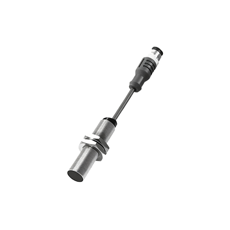
The output from the comparator is a logic-level signal that needs to interface with control systems like PLCs. The output stage is designed for robustness and noise immunity. For a standard three-wire DC sensor, this stage typically involves an NPN or PNP transistor (for NPN or PNO output types) driving the load. A flyback diode is mandatory across the load to suppress voltage spikes from inductive loads. For two-wire AC/DC sensors, the output is achieved through a switching element like a TRIAC or a power MOSFET in series with the supply lines. Current limiting resistors and snubber circuits (RC networks) are incorporated to protect the switching element from inrush currents and voltage transients. The choice of output type depends entirely on the application's control voltage and input requirements.
Capacitive Sensor Design Considerations
Capacitive proximity sensors operate on the principle of detecting changes in capacitance. The sensor forms one plate of a capacitor, with the target or environment acting as the other plate. The circuit often uses the sensor capacitance in a relaxation oscillator or an RC timing circuit. As a target approaches, the capacitance increases, altering the oscillator frequency or the charge/discharge time constant of an RC circuit. This change is measured, often by converting time or frequency to a voltage using a phase-locked loop (PLL) or a timer IC. Capacitive sensors are sensitive to all materials, not just metals, making them ideal for detecting liquids, plastics, or granular substances. A major design challenge is shielding and guarding to prevent false triggers from environmental humidity or contamination on the sensor face.
Power Supply Design and Protection
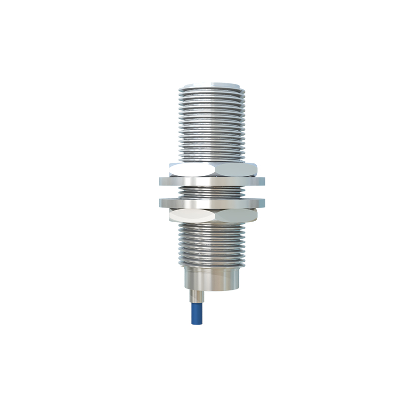
A stable and clean power supply is non-negotiable for consistent sensor performance. Most industrial sensors operate on a wide DC range (e.g., 10-30V DC). A voltage regulator, such as a low-dropout (LDO) regulator, provides a stable voltage for the sensitive oscillator and op-amp circuitry. Protection against reverse polarity is implemented using a series diode or a MOSFET-based circuit with lower voltage drop. Transient voltage suppression (TVS) diodes and ferrite beads are added to clamp voltage spikes and filter high-frequency noise from the supply lines, respectively. For sensors in harsh electrical environments, incorporating galvanic isolation using optocouplers in the signal or output path can prevent ground loops and damage from high common