Introduction to Photoelectric Sensors in Industrial Automation
Photoelectric sensors are indispensable components in modern industrial automation, serving as the "eyes" of a control system. These devices detect the presence, absence, or distance of objects using a light transmitter and receiver, without physical contact. Their applications range from simple object detection on conveyor belts to complex positioning tasks in assembly lines. When integrated with a Programmable Logic Controller (PLC), they form a robust system for automated decision-making and process control. The reliability, speed, and versatility of photoelectric sensors make them a preferred choice over mechanical limit switches in many demanding environments. Understanding their operational principles is the first step toward effective integration into a PLC-based control system.
Fundamentals of PLC Ladder Logic for Sensor Integration
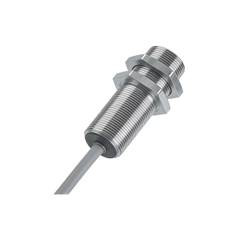
PLC ladder logic programming remains the most widely used language for industrial control due to its intuitive, relay-based symbolism. For photoelectric sensor integration, the programmer must comprehend the sensor's output type—typically either NPN (sinking) or PNP (sourcing)—and its corresponding wiring to the PLC input module. In ladder logic, a photoelectric sensor is represented as a normally open (NO) or normally closed (NC) contact instruction, depending on the desired logic. The core principle involves the sensor's signal altering the state of an input address in the PLC. This change is then processed by the ladder logic program to control outputs, such as actuators, motors, or indicators. A solid grasp of basic instructions like XIC (Examine If Closed) and XIO (Examine If Open) is crucial for building functional and efficient control routines.
Designing a Basic Object Detection Ladder Diagram
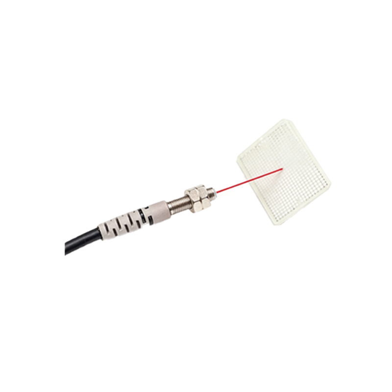
A fundamental application is detecting an object on a conveyor. Consider a diffuse photoelectric sensor positioned above the belt. When an object passes, it reflects the emitted light back to the receiver, triggering the sensor output. In the PLC program, this physical input (e.g., I:0/0) is linked to a ladder rung. A typical rung uses an XIC instruction addressed to I:0/0. When the sensor is activated (object present), the instruction becomes true, allowing power to flow to the next instruction on that rung. This could energize a timer (TON) to introduce a delay or directly latch an output coil (O:0/0) to activate a diverter arm. It is essential to include debouncing logic or a timer to prevent false triggers from vibration or ambient light fluctuations, ensuring system stability.
Implementing Advanced Control with Counter and Shift Register Functions
Beyond simple detection, photoelectric sensors often feed data into advanced PLC functions for complex sequencing. A common example is using a sensor paired with a counter (CTU) to track the quantity of items passing a point. Each sensor activation increments the counter's accumulated value. The ladder logic can compare this value to a preset limit using an EQU (Equal) instruction; once reached, it can trigger a batch process or stop the conveyor. Similarly, a shift register (e.g., BSL or FIFO instruction) can utilize sensor inputs to track an object's position through multiple stages of a production line. Each sensor pulse shifts a bit through the register, enabling coordinated actions at subsequent stations, such as drilling or labeling, based on the object's precise tracked location.
Integrating Multiple Sensors for Complex Machine Sequencing
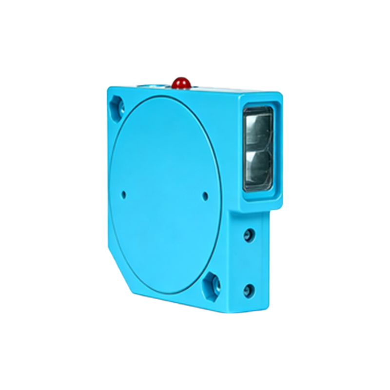
Sophisticated machines often employ multiple photoelectric sensors—retro-reflective, through-beam, and background suppression types—for different tasks. Programming this requires careful management of the PLC's input addresses and interlocking logic. For instance, a packaging machine might use one through-beam sensor to detect box presence at a loading station and a diffuse sensor to verify product insertion. The ladder logic must sequence these inputs using internal logic bits or sequencer instructions (SQO). Safety interlocking is critical; the program should be designed so that the cycle cannot proceed unless all preceding sensor conditions are met. This prevents jams and ensures operational integrity. Structured programming with subroutines for each machine section enhances readability and maintenance.
Best Practices for Troubleshooting and Maintenance
Even well-designed systems require maintenance. Common issues with photoelectric sensor PLC programs include false triggering, signal dropout, or incorrect sequencing. Effective troubleshooting starts with the PLC's diagnostic tools. Monitoring the logic status in real-time can verify if the physical sensor activation is correctly registering at the designated input address. If the input bit fails to energize, the problem likely lies in the field wiring, sensor alignment, or power supply. Within the program, ensure timer presets and counter values are correctly set for the application speed. Regularly comment your ladder logic rungs with descriptions of the sensor's purpose and expected behavior. Implementing fault routines that use sensor status bits to trigger alarms (e.g., "Sensor A Blocked") can significantly reduce downtime by guiding operators to the specific issue.
Conclusion and Future Trends
The integration of photoelectric sensors with PLC ladder logic forms the backbone of countless automated systems. Mastery of this integration allows engineers to create responsive, reliable, and efficient control solutions. The future points toward smarter sensors with integrated IO-Link communication, which can transmit detailed diagnostic data directly to the PLC, moving beyond simple on/off signals. This will enable predictive maintenance and more adaptive control strategies. However, the core programming principles of reading inputs, executing logic, and driving outputs will remain. Continuous practice in designing, simulating, and debugging ladder logic programs with various sensor types is the key to success in the evolving landscape of industrial automation.