Introduction to PNP 3-Wire Proximity Sensors
Proximity sensors are fundamental components in modern industrial automation, providing non-contact detection of metallic and, in some cases, non-metallic objects. Among the various configurations, the 3-wire DC sensor is the most prevalent, with PNP (Positive-Negative-Positive) and NPN (Negative-Positive-Negative) being the two primary output types. This article focuses on the operation, wiring, application, and advantages of the PNP 3-wire proximity sensor, a cornerstone in control systems where a positive switching signal is required. Understanding the distinction between PNP and NPN is crucial for proper integration and avoiding costly wiring errors in control panels and machinery.
Operating Principle and Internal Circuitry
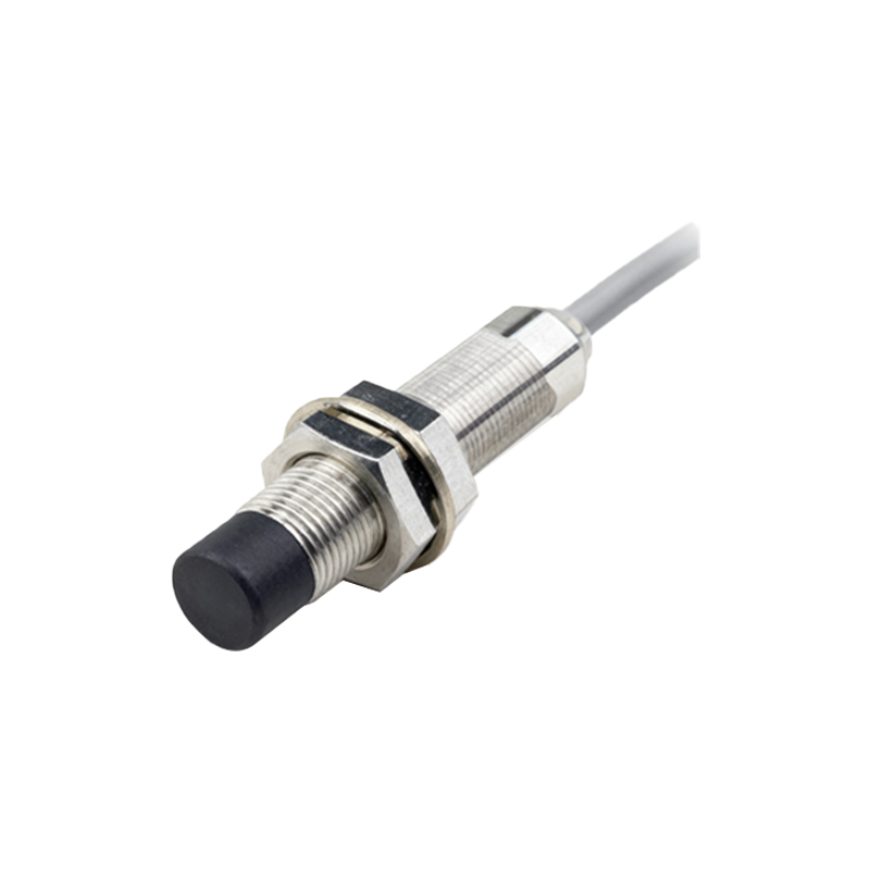
A PNP 3-wire proximity sensor consists of three distinct wires: brown (typically for positive supply voltage, +V), blue (for common negative or 0V), and black (the switched output signal). Internally, the sensor contains an oscillator circuit that generates a high-frequency electromagnetic field. When a target object enters this sensing field, it induces eddy currents, causing a change in the oscillation amplitude. This change is detected by a threshold circuit, which then triggers the output switching element. In a PNP sensor, the output switching device is a PNP transistor. In its normal, non-activated state (no target present), the black output wire is electrically disconnected (open circuit). When a target is detected, the internal PNP transistor switches ON, connecting the black output wire internally to the positive supply voltage (+V) on the brown wire. Thus, the sensor "sources" current to the load.
Standard Wiring Configuration and Sinking vs. Sourcing
Correct wiring is paramount. The standard color code (brown: +V, blue: 0V, black: output) is widely adopted per international standards like IEC 60947-5-2. The PNP sensor is connected as follows: the brown wire to the DC positive terminal (e.g., +24VDC), and the blue wire to the DC common or negative terminal (0VDC). The black output wire is connected to one terminal of the load (e.g., a PLC input, relay coil, or indicator lamp). The other terminal of the load is then connected to the common negative (0VDC). This configuration defines a "sourcing" output. The PNP sensor sources positive current from the supply to the load. This is often contrasted with NPN "sinking" outputs, where the load is connected to +V and the NPN sensor sinks current to 0V. A simple mnemonic is "PNP: Positive Switched, Plugs to Positive load terminal."
Key Advantages and Typical Applications
The PNP sourcing configuration offers several practical advantages. It aligns intuitively with the logic of many programmable logic controllers (PLCs) from European and global manufacturers, where a PLC input module is designed to receive a sourcing signal (the input card provides the 0V connection). This can simplify cabinet wiring. PNP sensors are also considered slightly safer in some fault scenarios, as an accidental short to ground on the output wire typically does not cause a permanent short circuit of the power supply. Common applications are ubiquitous: object detection on conveyor lines, part presence verification in assembly machines, end-of-travel positioning, rotary encoder indexing, and robotic arm positioning. They are the default choice in systems where the control logic is based on a "high" signal (24V) representing a TRUE or ON state.
Critical Considerations for Selection and Installation
Selecting the right PNP 3-wire sensor requires attention to several parameters beyond the output type. The sensing distance (rated and effective), target material (ferrous, non-ferrous, or all metal), housing material (metallic or non-metallic for immune sensing), and environmental protection rating (IP67, IP69K) are primary factors. Electrical specifications such as supply voltage range (commonly 10-30VDC), output current capacity, and switching frequency must match the application demands. During installation, ensure proper shielding and separation from high-voltage power lines to prevent electrical noise interference. Always refer to the manufacturer's datasheet for specific wiring diagrams, mounting clearances, and temperature ratings to ensure reliable, long-term operation in the intended industrial environment.
Troubleshooting Common Issues
Even with proper selection, issues can arise. A frequent problem is incorrect wiring, often confusing PNP with NPN. Symptoms include the sensor's indicator LED lighting but no signal at the load