Introduction to Response Speed in Proximity Sensing
In industrial automation and control systems, the response speed of a proximity sensor is a critical performance parameter that directly impacts system efficiency, precision, and safety. Response speed, often measured in milliseconds (ms) or microseconds (µs), refers to the total time delay between the moment a target object enters the sensor's detection zone and the moment the sensor's output signal changes state. This encompasses both the sensor's internal processing time and the time for the output circuit to react. A faster response enables higher machine cycle speeds, improved synchronization in complex processes, and enhanced capability to detect rapidly moving objects. Engineers must thoroughly understand the factors influencing this speed to select the optimal sensor for a given application and to troubleshoot performance bottlenecks effectively.
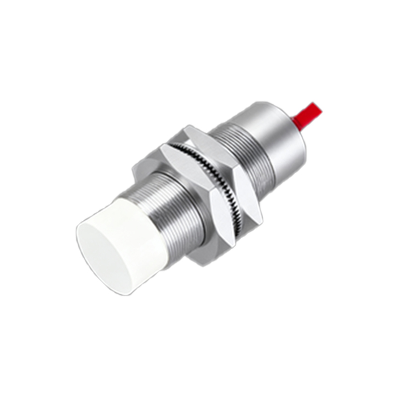
Core Factors Influencing Sensor Response Time
Several intrinsic and extrinsic factors determine how quickly a proximity sensor can react. The sensing technology itself is primary. Inductive sensors, detecting metallic objects, typically offer very fast response times, often ranging from 50 µs to 2 ms. Capacitive sensors, used for non-metallic materials, generally have slightly slower response due to the nature of capacitance change measurement. Photoelectric sensors, depending on their mode (through-beam, retro-reflective, diffuse), can have variable speeds, with modulated LED types providing fast response but potentially slower than some inductive models. Beyond technology, the sensor's internal oscillator frequency, signal processing circuitry, and output type play huge roles. A sensor with a transistor output (PNP/NPN) is inherently faster than one with a mechanical relay output. The design of the ASIC (Application-Specific Integrated Circuit) and the algorithms for hysteresis and noise immunity also introduce processing delays that affect overall speed.

The Impact of Target Characteristics and Environment
The object being detected significantly influences achievable response speed. For inductive sensors, the target material (steel, aluminum, copper), size, and shape affect the strength and speed of eddy current generation. A larger, ferrous steel target placed squarely within the sensing face will trigger a faster, stronger signal than a small, thin, or non-ferrous target. The approach direction and speed of the target are equally crucial. For reliable detection, the sensor must be given enough "dwell time" within its active zone to complete its switching cycle. A very fast-moving small target may pass through the detection field too quickly for the sensor to register it. Environmental conditions like extreme temperatures, strong electromagnetic interference (EMI), or contamination (oil, dust) can also degrade signal quality, forcing the sensor's circuitry to employ more aggressive filtering, which slows down the effective response.
Measuring and Interpreting Response Speed Specifications
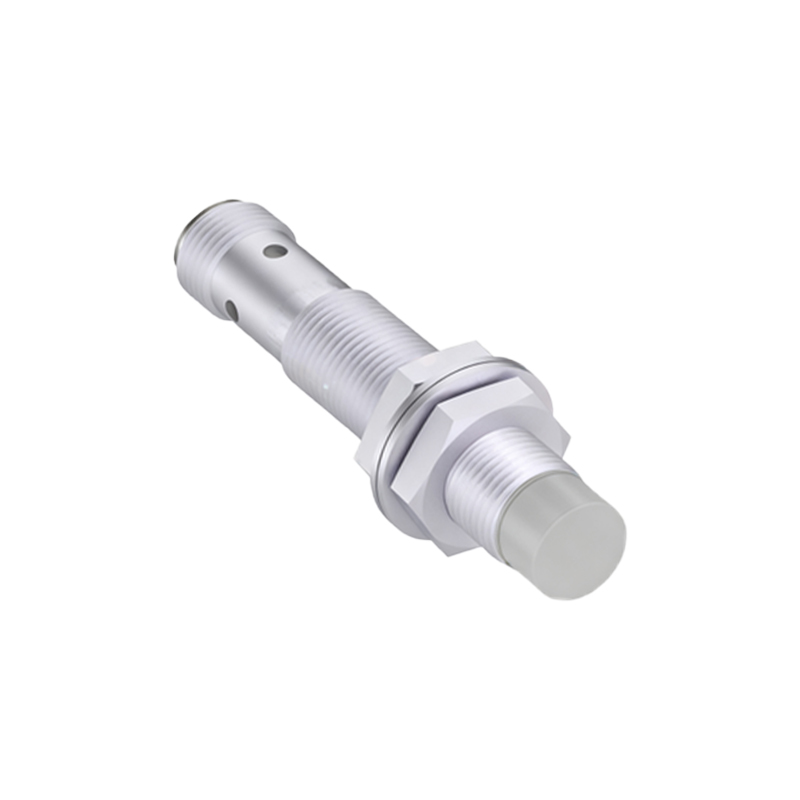
Manufacturers specify response speed in datasheets using standardized tests. Key parameters include "Response Time" (the delay from target presence to output switch) and "Reset Time" (the delay from target absence to output return). Often, a "Switching Frequency" is provided, calculated as the reciprocal of the total response cycle time (Response + Reset). For example, a sensor with a 1 ms response and 1 ms reset time has a cycle of 2 ms, equating to a maximum theoretical switching frequency of 500 Hz. It is vital to understand that these are typically maximum values under ideal laboratory conditions: a standard target (often 1mm thick mild steel), optimal distance, and a clean electrical environment. Real-world performance will often be slower. Engineers must always derate these figures, considering safety factors, especially in high-speed or safety-critical applications.
Optimization Strategies for Maximum Speed
To achieve the fastest possible system response, a holistic approach is necessary. First, select a sensor with a technology and specification that exceeds the minimum requirement of the application. If detecting metal at high speed, a high-frequency inductive sensor with a short-body design and a fast NPN/PNP output is ideal. Second, optimize installation: ensure the target is as large and conductive as possible, approaches the sensor head-on, and is positioned at the recommended operating distance, not the maximum sensing distance. Using the teach-in or potentiometer functions, set the sensing distance as tight as possible to the actual target to minimize unnecessary dead band. Third, ensure clean electrical power and proper shielding of cables to reduce noise, allowing the sensor to operate with minimal internal filtering. Finally, integrate the sensor with a high-speed controller input module designed for fast pulse catching.
Application Examples and Trade-Offs
In a bottling plant, photoelectric sensors counting bottles on a conveyor require fast response to prevent miscounts at high line speeds. Here, a modulated diffuse sensor with a high switching frequency is chosen. In a CNC machine, an inductive sensor detecting the