Introduction to Photoelectric Sensors
Photoelectric sensors are essential components in industrial automation, utilizing light beams to detect the presence, absence, or distance of objects. These sensors operate by emitting a light source—typically infrared, visible red, or laser—and measuring the reflection or interruption of that light. Common types include through-beam, retro-reflective, and diffuse reflective sensors, each suited for specific applications based on range, environmental conditions, and target properties. Their versatility makes them ideal for tasks such as object counting, positioning, and quality control in manufacturing lines, logistics, and safety systems. Understanding the basic principles helps in selecting the right sensor for optimal performance and reliability.
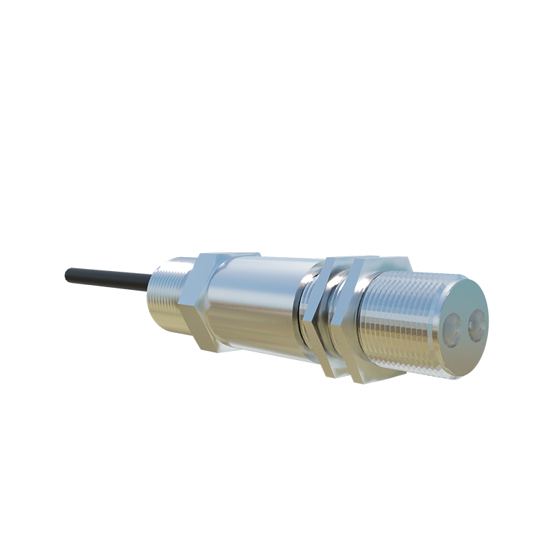
Key Components and Image Examples
A typical photoelectric sensor consists of an emitter, receiver, and housing. The emitter projects light, while the receiver detects changes in the light pattern. Images often show compact, rugged designs with LED indicators for status monitoring. For instance, through-beam sensors feature separate emitter and receiver units, visible in diagrams as two distinct devices aligned opposite each other. Retro-reflective models include a built-in reflector, depicted with a single unit bouncing light off a reflective tape. Diffuse sensors appear as standalone devices with both emitter and receiver in one housing, illustrated in close-up shots highlighting lens configurations. High-resolution images aid in identifying part numbers, connection terminals, and mounting brackets, crucial for installation and maintenance.
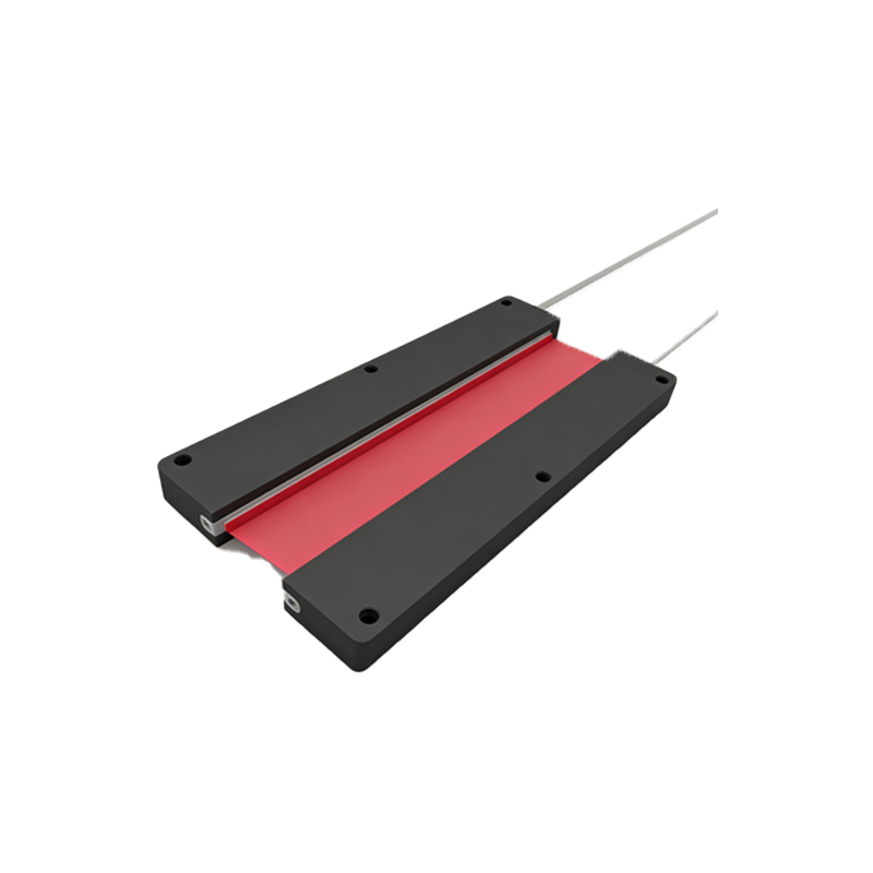
Position Marking Standards and Symbols
Position markings on photoelectric sensors ensure correct alignment and installation. Standard symbols include arrows indicating the sensing direction, often etched on the housing or shown in manuals. For example, through-beam sensors may have alignment marks on the emitter and receiver to guide precise facing. Retro-reflective units often feature a reflector symbol near the lens. Diagrams frequently use dotted lines to represent the light beam path, with labels for effective sensing ranges. Additionally, color codes—such as green for power and yellow for output—are common in wiring diagrams. Adhering to these markings prevents errors like misalignment or incorrect wiring, which can lead to sensor failure or reduced accuracy.
Installation Guidelines with Visual Aids
Proper installation maximizes sensor performance. Start by mounting the sensor securely using provided brackets, ensuring it is free from vibrations. Images demonstrate ideal placements: for through-beam types, the emitter and receiver should be directly opposite, with the beam path clear of obstructions. Retro-reflective sensors require the reflector within the specified angle and distance, shown in side-view diagrams. Diffuse sensors need to be positioned at an optimal distance from the target, considering factors like color and surface texture—illustrations often include distance charts. Wiring diagrams depict connections to power supplies and controllers, with emphasis on shielding cables to avoid electrical noise. Always refer to manufacturer visuals for specific models.
Common Applications and Setup Images
Photoelectric sensors are used in diverse settings. In conveyor systems, images show sensors mounted along belts to detect package presence or count items. For automated doors, diagrams highlight sensors placed at entry points for safety beams. In robotics, close-ups illustrate sensors on grippers for object positioning. Each application includes setup images with annotations: for example, a bottling plant might display sensors aligned at fill levels, with markers indicating tolerance zones. Troubleshooting galleries often compare correct and incorrect installations, such as misaligned beams causing false triggers. These visuals help engineers replicate successful setups and avoid common pitfalls in real-world environments.
Maintenance and Calibration Tips
Regular maintenance ensures long-term reliability. Images guide cleaning procedures: use a soft cloth to wipe lenses, avoiding scratches that could scatter light. Calibration involves adjusting sensitivity potentiometers, depicted with screwdriver positions on sensor housings. Diagrams may show test targets—like white cards for diffuse sensors—to verify detection ranges. For retro-reflective types, check reflectors for dirt or damage, illustrated in before-and-after photos. Logging alignment marks over time helps monitor drift, with sample logs included in manuals. If issues arise, diagnostic LEDs provide visual cues; reference images decode blinking patterns for faults like overload or weak signals. Always power off during maintenance to prevent damage.
Advanced Features and Future Trends
Modern photoelectric sensors incorporate advanced features like background suppression, taught through images showing adjustable sensing fields. Laser sensors offer high precision, with diagrams highlighting fine beam spots for small part detection. Smart sensors with IO-Link connectivity are depicted with network diagrams, enabling remote monitoring. Emerging trends include miniaturization for compact spaces and enhanced durability in harsh conditions, illustrated in cross-sectional views of sealed housings. Future developments may integrate AI for adaptive sensing, visualized in concept sketches. Staying updated with technical imagery helps engineers leverage new technologies for improved efficiency and innovation in automation projects.