Introduction to Photoelectric Sensor Wiring
Photoelectric sensors are indispensable components in modern industrial automation, providing non-contact detection of objects. Their operation relies on emitting a light beam (visible, infrared, or laser) and detecting changes in the received light. A critical aspect of their installation and functionality is the electrical wiring, which connects the sensor to a power source and a control system, such as a Programmable Logic Controller (PLC). Proper wiring ensures reliable operation, safety, and longevity of the sensor and the entire system. This guide focuses specifically on the wiring procedures for models equipped with a push-button configuration for simplified setup and testing.
Understanding Push-Button Functionality
Many advanced photoelectric sensors feature integrated push buttons. These are not for mechanical actuation but for electronic configuration. Typically, these buttons allow for functions like teaching (setting the sensing distance or threshold), switching between light-on/dark-on operation modes, or initiating a manual test cycle. This functionality eliminates the need for separate potentiometers or complex programming tools, streamlining the setup process. When examining a wiring diagram, the presence of a push-button symbol usually indicates these built-in smart features, which interact with the sensor's internal logic rather than the main power circuit.
Standard Terminal Designations and Colors
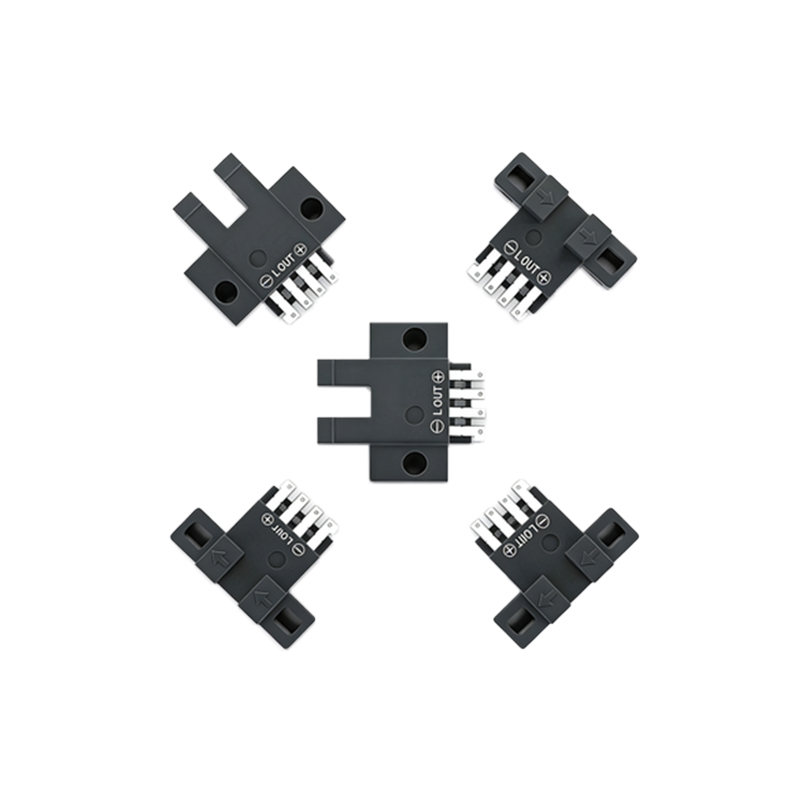
Before consulting a specific diagram, understanding common terminal markings is crucial. A typical 3-wire DC sensor will have the following connections: Brown wire (or +V): This is the positive power supply terminal, usually connecting to a 10-30V DC source. Blue wire (or 0V): This is the negative power supply terminal, connected to the DC common or ground. Black wire (or OUT): This is the switched output signal wire. In a sinking (NPN) sensor, the black wire provides a path to 0V when active. In a sourcing (PNP) sensor, it provides a path to +V when active. The push-button function is often internally connected between the output logic and the teaching circuit, not represented as a separate physical wire in the main power loop.
Analyzing a Typical Wiring Diagram
A standard wiring diagram for a push-button photoelectric sensor will show the following elements. First, the power supply section: the brown and blue wires connected to a stabilized DC power source, with a fuse for protection. Second, the load section: the black output wire connected to the input terminal of a PLC, relay, or other controller. The other side of this load connects to the opposite power rail (e.g., for an NPN sensor, the PLC input's common would connect to +V). A dotted line or a separate symbol labeled "TEACH" or "SET" with a push-button icon represents the configuration button. The diagram will note that pressing this button while power is applied triggers the teaching mode, often indicated by an LED blink pattern.
Step-by-Step Wiring Procedure
Begin by disconnecting all power to the circuit. Identify the sensor's model number and locate its specific datasheet and wiring diagram. Mount the sensor securely. Connect the brown wire to the positive DC supply terminal (e.g., +24V). Connect the blue wire to the negative DC supply terminal (0V or common). Connect the black output wire to the input device (e.g., PLC input channel X0). Connect the common side of the input device according to the sensor type: for NPN (sinking), connect the PLC common to +V; for PNP (sourcing), connect it to 0V. Once connections are verified for correctness and tightness, apply power. Use the push button as per the manual to configure the sensing parameters.
Configuration via the Push Button
After wiring and powering the sensor, the push button is used for setup. A common sequence is: Power on the sensor. Aim the sensor at the target object at the desired detection distance. Press and hold the push button for approximately 3 seconds until the indicator LED changes (e.g., from green to orange). Release the button. The sensor now stores the received light level as the detection threshold. The LED will typically confirm with a steady or blinking pattern. This simple process replaces manual sensitivity adjustment screws. Always refer to the specific product manual, as button press duration and LED patterns can vary between manufacturers and models.
Safety Precautions and Best Practices
Always follow lock-out/tag-out procedures before handling wiring. Use the correct wire gauge suitable for the sensor's current rating. Employ ferrules on stranded wires for secure termination in screw terminals. Ensure the power supply voltage matches the sensor's rated voltage. Pay close attention to the sensor type (NPN vs. PNP) and wire the load correctly to avoid short circuits. Shielded cable is recommended for long cable runs or in electrically noisy environments, with the shield grounded at one end only. The push-button interface is for low-voltage logic; never apply external voltage to it. Regularly inspect connections for corrosion or looseness.
Troubleshooting Common Wiring Issues
If the sensor does not operate, first check the power indicator LED. If it is off, verify power supply voltage and polarity at the sensor terminals. If the power LED is on but there is no output, use the push button to initiate a manual test. Many sensors will force the output active when the button is pressed briefly during operation, helping to isolate whether the fault is in the sensor's detection circuit or the external wiring/load. Check for loose connections, especially on the black output wire and the load's common connection. Verify that the load (e.g., PLC input) is functioning correctly and is compatible with the sensor's output type and current. Incorrect NPN/PNP wiring to the controller is a very common error.
Conclusion and Final Verification
Correctly wiring a photoelectric sensor with a push-button interface is a straightforward process when following the manufacturer's diagram and guidelines. The key steps are: proper identification of wires, secure connection to the correct power and load terminals, and accurate configuration using the integrated button. After wiring and configuration, perform a final system test. Trigger the sensor by passing an object through its beam and verify the response at the control system. The push-button feature greatly simplifies setup and maintenance, making these sensors highly user-friendly. Proper installation ensures optimal performance, minimizes downtime, and enhances the reliability of your automated system.