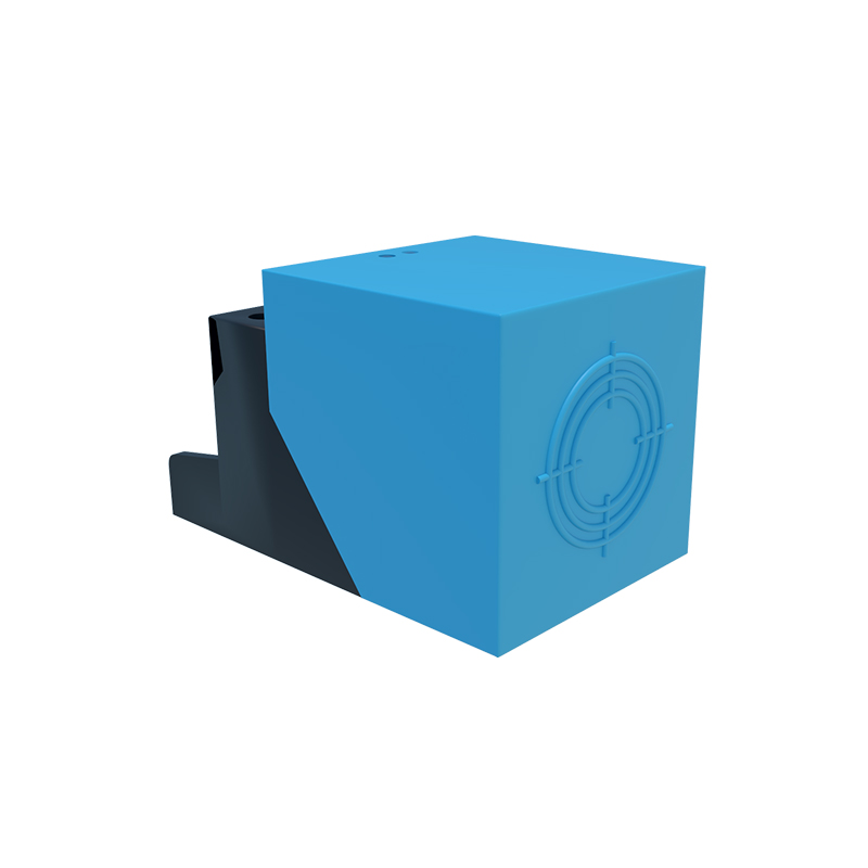
In the world of industrial automation and electrical engineering, clear communication is paramount. Electrical diagrams, schematics, and ladder logic form the universal language for designing, installing, and troubleshooting complex systems. Among the most critical components in these systems are proximity switches, non-contact sensors that detect the presence or absence of an object. Understanding their standardized symbols is essential for any professional working with control circuits. Unlike basic switches, proximity sensors are represented by a combination of graphical elements that convey their type, function, and electrical output.
The foundation of all proximity sensor symbols is the basic switch symbol: a line representing the contact point, with a hinged or angled line to indicate the actuator. For a standard limit switch activated by physical pressure, this actuator line might end in a small circle or bump. The key differentiator for a proximity switch is the addition of a distinctive diamond shape attached to this actuator point. This diamond is the universal schematic symbol denoting a non-contact sensing function. It immediately tells the reader that this switch is activated without physical touch, through an electromagnetic field, ultrasonic beam, or optical light.
Beyond this common diamond, symbols become more specific to indicate the sensing technology. Inductive proximity sensors, which detect metallic objects, are often represented with the standard switch-diamond combination, sometimes accompanied by additional notation like "IN" or a coil-like symbol nearby to imply the electromagnetic field. Capacitive sensors, capable of detecting both metallic and non-metallic materials, may use a similar symbol but might be annotated with "CAP" or have two parallel lines near the sensing face, suggesting the capacitive plates. Photoelectric sensors, using a light beam, have a more varied representation. They are frequently shown as two separate symbols: a transmitter (often a circle with a diode arrow pointing out) and a receiver (a circle with a diode arrow pointing in), connected by a dashed or dotted line representing the light beam. The switch output is then tied to the receiver component. Ultrasonic sensors may use symbols resembling two small loudspeakers or concentric arcs to represent sound waves.
The output type of the sensor is another critical piece of information encoded in the symbol. This is shown within the switch portion itself. A standard normally open (NO) contact is depicted with the contact line and actuator line separated. A normally closed (NC) contact shows these lines connected. For a solid-state electronic proximity sensor, the switch symbol is often enclosed in a circle or a square, representing the integrated electronics and housing. The output configuration—whether it's a PNP (sourcing) or NPN (sinking) transistor output—is rarely detailed in the symbol itself but is always specified in the accompanying component list or part number. However, some detailed schematics may annotate the symbol with "+", "-", and "out" labels to clarify the wiring.
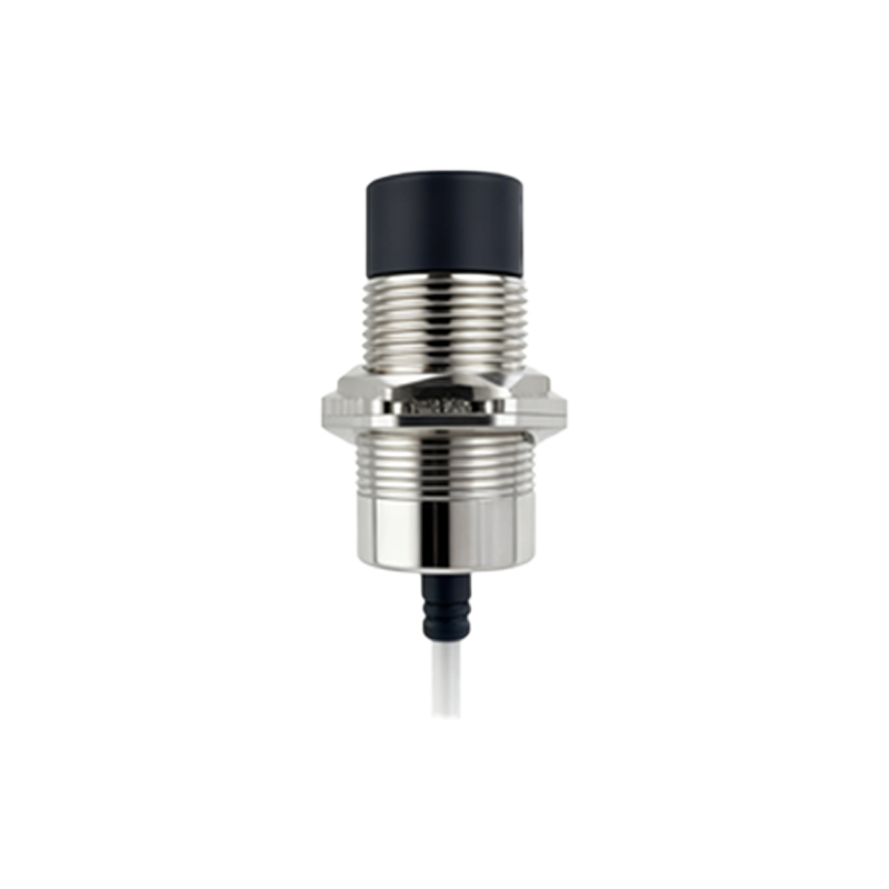
Reading a diagram involves putting these elements together. For instance, a symbol showing the basic switch with a diamond, a circle around it, and the contacts in the open position represents a solid-state, normally open, inductive proximity sensor. When this symbol is placed in a ladder logic rung, it defines the logic condition for activating an output, like a solenoid or motor starter. Misinterpreting the symbol—for example, confusing a normally open for a normally closed—can lead to incorrect wiring and dangerous operational faults. Therefore, always cross-reference the schematic symbol with the manufacturer's datasheet for the specific model in use.
Mastering these symbols is not merely an academic exercise. It enables technicians to quickly trace circuits, diagnose failures (such as a sensor not detecting a part), and understand the intended machine sequence. As automation evolves, symbols remain the constant, ensuring that a schematic drawn in one country is perfectly intelligible to an engineer on the other side of the globe. Whether you are designing a new packaging line or maintaining a robotic cell, fluency in the language of proximity switch sensor symbols is a fundamental skill for safety, efficiency, and precision in modern industrial systems.