Introduction to Infrared Proximity Sensing Technology
Infrared proximity sensors are fundamental components in modern robotics and automation, operating on the principle of emitting infrared light and measuring the intensity of the reflected signal. This non-contact detection method is highly effective for obstacle avoidance, distance measurement, and line following. The core components typically include an IR LED emitter and a photodiode or phototransistor receiver. When an object is within range, the emitted IR light reflects off its surface and is captured by the receiver. The strength of this received signal is inversely proportional to the distance, allowing the system to gauge proximity. This technology is favored for its simplicity, low cost, and reliability, making it an ideal choice for educational robotics projects and basic autonomous vehicle platforms.
Core System Architecture of an IR Sensor Car
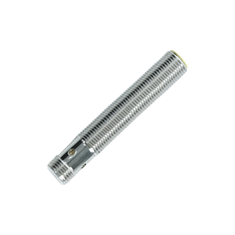
A basic infrared proximity sensor car is built around a modular architecture. The central processing unit is typically a microcontroller like an Arduino Uno or an ESP32, which serves as the brain of the operation. It reads analog or digital signals from multiple IR sensor modules mounted on the chassis—commonly at the front and sometimes on the sides. These sensors are connected to the MCU's input pins. The output side of the MCU is connected to a motor driver module, such as an L298N or L293D, which provides the necessary current and voltage to drive the DC gear motors attached to the wheels. A separate power supply, often a battery pack, is crucial to ensure stable voltage for both the logic circuits and the motor drivers, preventing noise interference on the sensor lines.
Sensor Calibration and Environmental Considerations
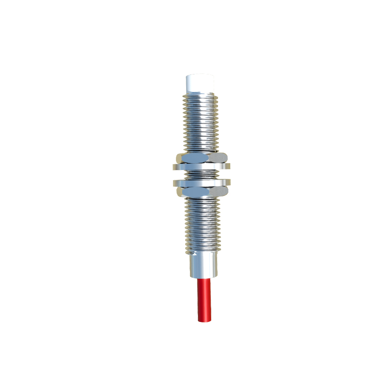
Calibration is a critical step for ensuring accurate and consistent performance from IR sensors. Due to variations in component tolerances and environmental factors like ambient light and surface reflectivity, each sensor must be tuned. The process involves placing the sensor at a known reference distance from a standard surface and adjusting a potentiometer on the sensor module or setting threshold values in the code. A major challenge is infrared interference from sources like sunlight or incandescent bulbs, which can saturate the receiver. This is often mitigated by modulating the emitted IR signal at a specific frequency (e.g., 38 kHz) and tuning the receiver to the same frequency, effectively filtering out background noise. Choosing the right sensor for the surface color and texture is also vital, as dark, matte surfaces absorb IR light, reducing effective range.
Programming Logic for Autonomous Navigation
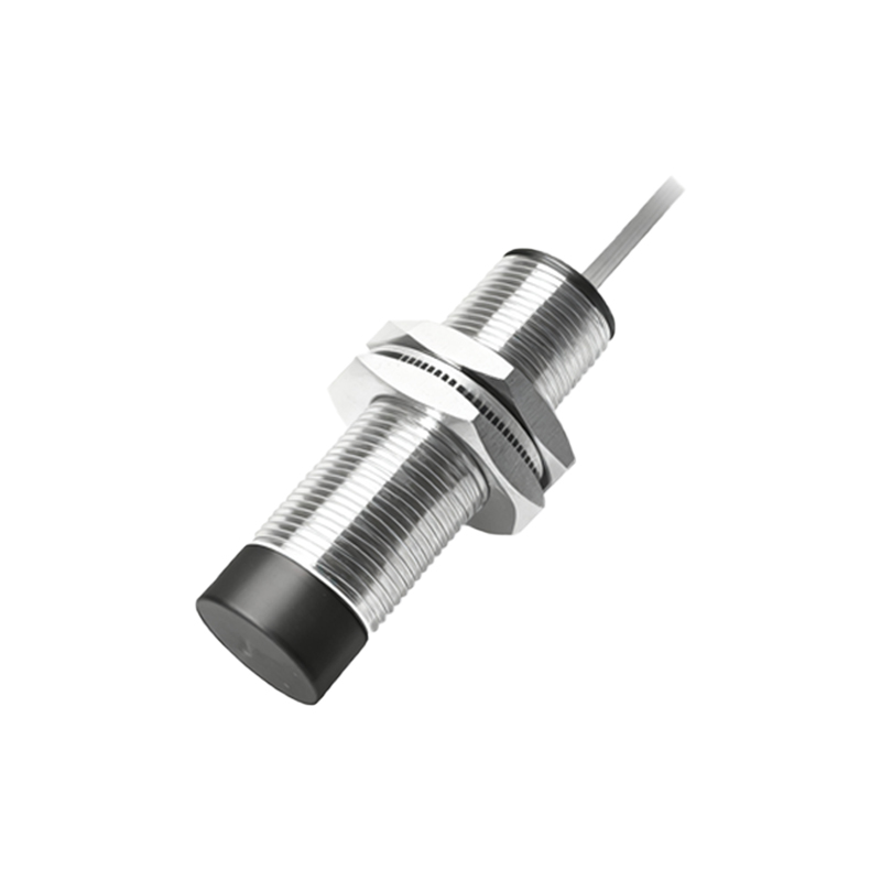
The intelligence of the car is defined by its firmware. A standard obstacle-avoidance algorithm involves continuously polling the front-mounted IR sensors. The code logic can be structured as: if the left sensor detects an obstacle, the car turns right; if the right sensor detects one, it turns left; if both sensors detect an obstacle, the car reverses and then turns. More advanced implementations use state machines or proportional control for smoother maneuvers. For line-following applications, an array of IR sensors is used to track a contrasting line on the ground. The microcontroller reads the pattern from the array and adjusts the motor speeds differentially to keep the car centered on the line. Efficient code utilizes non-blocking techniques and timer interrupts to ensure responsive sensor polling while managing motor control tasks.
Practical Applications and Advanced Integrations
Beyond basic educational kits, IR sensor cars form the foundation for numerous practical applications. They are used in automated guided vehicles (AGVs) within warehouses for material transport, in domestic robotic vacuums for room navigation and cliff detection, and in smart toys. Advanced integrations involve fusing IR sensor data with inputs from other sensors like ultrasonic rangefinders for more robust distance measurement, or inertial measurement units (IMUs) for dead reckoning. Integrating wireless communication modules like Bluetooth or Wi-Fi allows for remote telemetry data monitoring and over-the-air updates to the control algorithm, transforming the simple car into a platform for IoT and robotics research.
Troubleshooting Common Development Issues
Developers often encounter specific issues during construction. Erratic motor behavior can stem from power supply insufficiency or electrical noise; solving this requires using decoupling capacitors and ensuring separate power rails for motors and logic. Inconsistent sensor readings may be due to improper calibration, interference, or faulty wiring. Systematic debugging involves checking voltage levels with a multimeter, verifying connections, and isolating the sensor in a controlled environment. Another common issue is mechanical instability, where sensor mounting vibrations affect readings, necessitating secure fastening and possibly vibration-damping materials. Documenting each step and testing subsystems independently before full integration is a best practice that saves significant development time.