Understanding Photoelectric Sensor Basics
Photoelectric sensors are indispensable components in modern industrial automation, utilizing light beams to detect the presence, absence, or distance of objects. These sensors operate primarily through three main sensing methods: through-beam, retro-reflective, and diffuse reflective. Each method has distinct wiring and installation requirements, making a proper wiring diagram crucial for system reliability. The core electrical components typically involve a light emitter (often an LED) and a receiver, which must be correctly integrated into a control circuit. Understanding the sensor's output type—whether it is NPN (sinking) or PNP (sourcing)—is the foundational step before examining any wiring schematic, as this determines the compatibility with programmable logic controllers (PLCs) and other control devices.
Key Components in Wiring Diagrams
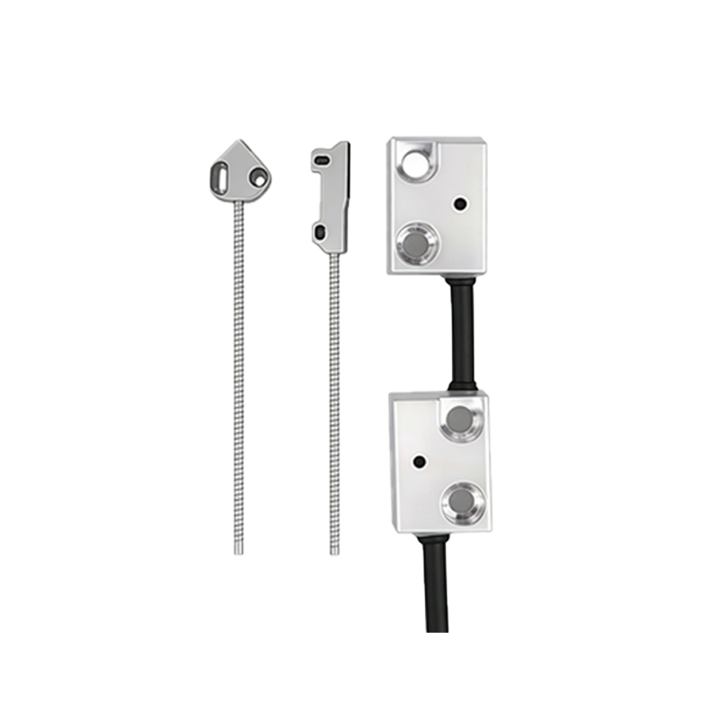
A standard photoelectric sensor wiring diagram includes several key terminals that must be connected precisely. These usually are: the positive supply voltage (V+ or brown wire), the ground (0V or blue wire), and the output signal wire (black or white wire). Some models feature additional wires for function selection, such as light-on/dark-on mode switching or timer settings. The diagram also illustrates protective elements like short-circuit and reverse polarity protection circuits. It is vital to cross-reference the manufacturer's datasheet, as wire color codes and terminal designations can vary between brands like Omron, Sick, or Keyence. The housing, often rated IP67 for durability, includes a cable gland or connector that must be properly sealed according to the conduit diagram.
Step-by-Step Wiring Procedure
Begin by disconnecting all power sources to prevent electrical hazards. Identify the sensor's operating voltage range (commonly 10-30V DC) and ensure the power supply matches. For a typical three-wire DC sensor, connect the brown wire to the positive DC supply and the blue wire to the negative or ground. The output wire (black) is then linked to the load (e.g., a PLC input module). If using a four-wire sensor with dual outputs, refer to the diagram to distinguish between normally open (NO) and normally closed (NC) contacts. Secure all connections using appropriate wire ferrules and terminals, and route cables through designated conduit entries as shown in the piping layout to minimize electromagnetic interference and physical strain.
Conduit and Cable Management Considerations
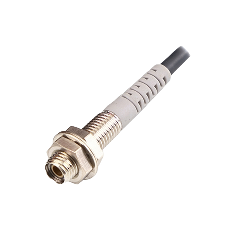
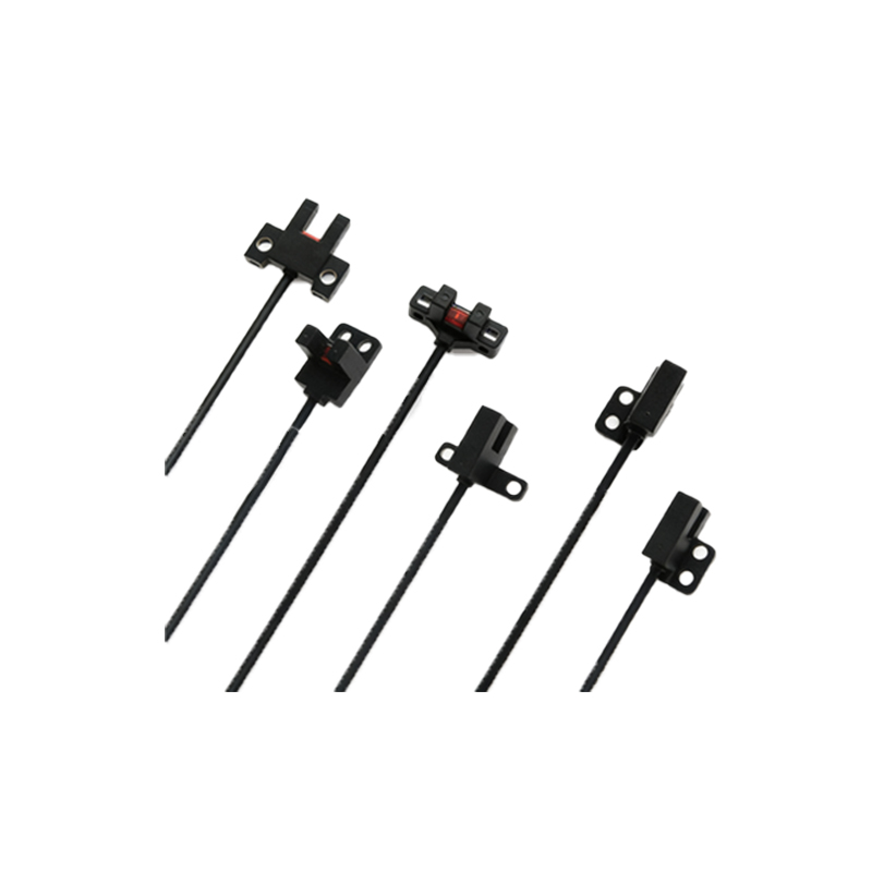
Industrial environments demand robust cable management to ensure sensor longevity. The wiring conduit diagram specifies the path for sensor cables from the device to the control cabinet, detailing bends, junction boxes, and sealing methods. Use flexible conduits (e.g., PG7 or NPT threaded types) for areas with vibration or movement. Maintain separation between sensor cables and high-power lines to avoid noise-induced false triggering. Ground shielding of cables in metal conduits is often recommended in diagrams to enhance EMI/RFI immunity. Adhere to local electrical codes (such as NEC or IEC standards) for conduit fill capacity and grounding practices, which are frequently annotated in professional diagrams.
Troubleshooting Common Wiring Issues
Incorrect wiring is a leading cause of sensor malfunction. If the sensor fails to operate, first verify voltage at the terminals with a multimeter, checking for loose connections or reversed polarity. Consult the wiring diagram to confirm if the output is configured for light-on or dark-on operation—misconfiguration here can lead to inverted logic. Intermittent signals may stem from inadequate cable shielding or ground loops; ensure all grounds are tied to a single point as per the schematic. For sensors in series or parallel configurations, recalculate the load current to prevent overloading the output transistor. Always compare the actual installation against the provided conduit and wiring diagram to identify physical discrepancies like pinched cables or improper gland sealing.
Advanced Applications and Integration
Beyond basic detection, photoelectric sensors with analog outputs or IO-Link communication require more complex wiring. Diagrams for these models include additional terminals for analog voltage/current signals (0-10V, 4-20mA) or data lines, which integrate directly into networked systems. When daisy-chaining multiple sensors on a single bus, the conduit plan must account for trunk and drop line layouts. Always follow the manufacturer's network wiring guidelines to maintain signal integrity. For safety-rated sensors (e.g., Type 4 PL e), the diagrams incorporate monitored outputs and cross-circuit detection, necessitating strict adherence to ensure compliance with machinery safety standards.
Maintenance and Best Practices
Regular maintenance, guided by the original wiring and conduit diagrams, prolongs sensor life. Periodically inspect cable integrity, connector corrosion, and conduit seals. Document any wiring modifications on the diagram to aid future troubleshooting. When replacing a sensor, use an identical model or one with a compatible wiring pinout to avoid re-engineering the circuit. Training personnel to read and interpret these diagrams accurately reduces downtime and enhances operational safety. Ultimately, a well-drawn photoelectric sensor wiring diagram is not just an installation tool but a critical reference for the entire lifecycle of the automation system.