Understanding Proximity Sensor Fundamentals
Before diving into programming, it's crucial to grasp the operational principles of proximity sensors. These non-contact devices detect the presence or absence of an object within their sensing field. Common types include inductive (for metals), capacitive (for various materials including liquids), and photoelectric sensors. Each type generates a distinct electrical signal—typically a digital ON/OFF signal or an analog current/voltage output—based on target detection. The core programming task involves configuring the sensor to interpret this signal correctly and trigger the desired action in a control system, such as a PLC (Programmable Logic Controller), microcontroller, or dedicated industrial controller. Understanding the sensor's datasheet parameters, like sensing range, hysteresis, and output type (NPN/PNP, NO/NC), is the mandatory first step.
Initial Hardware Setup and Wiring
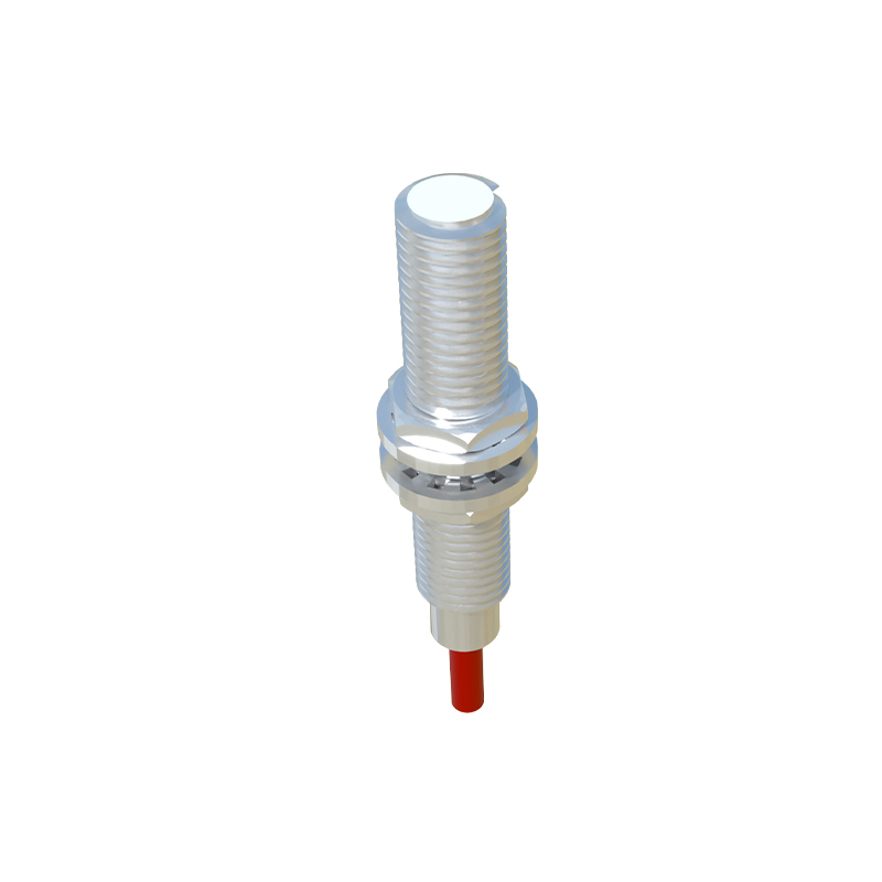
Proper physical installation is foundational to successful programming. Begin by mounting the sensor securely, ensuring the target object will pass within its specified sensing range and avoiding interference from other metal objects or electrical noise. Connect the sensor's power supply wires (usually brown for +V DC and blue for 0V DC) to a stable power source matching its voltage rating (e.g., 10-30V DC). Next, connect the output wire (often black for NPN or black/white for PNP) to the input channel of your controller. For analog sensors, connect the analog output wire to the controller's analog input module. Always implement shielding and proper grounding as per manufacturer guidelines to prevent erratic behavior, which could be mistaken for a programming error.
Configuring Basic Parameters via Teach-In or DIP Switches
Many modern proximity sensors feature simplified programming methods. For sensors with a 'Teach-In' function, programming involves presenting the target object at the desired detection point and activating the teach button (either physically or via a remote input). The sensor automatically stores the threshold value. For sensors with DIP switches, use a small tool to set switches for parameters like output logic (Light/Dark ON for photoelectric), operating mode (short-range/long-range), and time delays. Consult the manual for the specific switch coding. This step essentially 'programs' the sensor's onboard logic without needing external software, making it ideal for straightforward applications.
Programming within a PLC Ladder Logic Environment
Integrating the sensor with a PLC is a common industrial task. After wiring the sensor to a PLC input (e.g., I0.0), the programming occurs in the PLC software (e.g., TIA Portal, RSLogix). In Ladder Logic, the sensor's input contact is used as a condition. For a digital sensor, simply use the input address as a normally open (XIC) or normally closed (XIO) instruction to control an output coil or internal logic. For instance, a rung might be:| I0.0 |---( O0.0 )|, meaning output O0.0 energizes when sensor input I0.0 is active. For analog sensors, use a MOV instruction or a scaling function block (like SCALE in Siemens S7) to convert the raw analog input value (e.g., 0-27648) into a usable engineering unit (e.g., 0-10 mm).
Implementing Advanced Functions and Logic
Beyond simple detection, programming enables advanced functionalities. Utilize timer instructions (TON, TOF) to introduce on-delay or off-delay, filtering out signal chatter. Counter instructions (CTU) can be programmed to count objects detected by the sensor. For precise positioning with analog sensors, create comparison logic (EQU, GRT, LES) to trigger actions at specific distance thresholds. In complex systems, program the sensor's signal as part of a state machine or sequence logic, where its detection is a condition to move from one automated step to the next. Always include fault detection logic, such as monitoring for a sensor signal that is perpetually ON or OFF outside of normal machine cycles.
Calibration, Testing, and Troubleshooting
After programming, calibration is essential for accuracy, especially for analog and capacitive sensors. Use the controller's software to monitor the live sensor value. Adjust the sensor's position or potentiometer (if available) while observing the readout for the actual target. For digital sensors, verify the switching point. Conduct rigorous testing by running the target object through the entire range of expected conditions. Common troubleshooting steps include checking the LED indicator on the sensor, verifying power and wiring with a multimeter, monitoring the PLC input status table to see if the signal is being received, and reviewing program logic for errors. Ensure the programmed response time aligns