Introduction to the FA12-4KA Proximity Sensor
The FA12-4KA represents a robust and reliable solution in the realm of inductive proximity sensors. Engineered for industrial automation, this sensor is designed to detect the presence of metallic objects without any physical contact. Its core principle of operation relies on generating an electromagnetic field. When a metallic target enters this field, it induces eddy currents, causing a change in the field's oscillation amplitude. This change is detected by the sensor's internal circuitry, which subsequently triggers a switching signal. The "FA" series is renowned for its durability in harsh environments, and the FA12-4KA model, with its specific 4mm sensing distance and DC 3-wire configuration, is a common choice for precise positioning and object detection tasks in machinery and automated systems.
Key Technical Specifications and Features
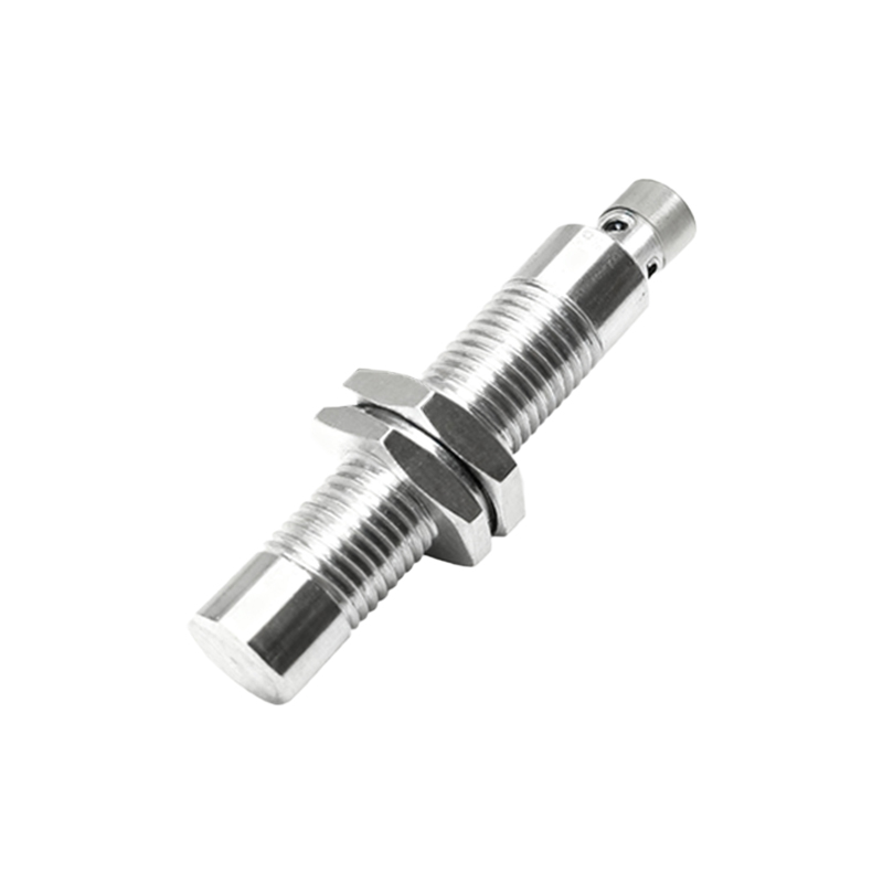
The performance of the FA12-4KA is defined by a clear set of technical parameters. It typically operates on a DC supply voltage ranging from 10 to 30V DC. The output is a solid-state NPN normally open (NO) transistor, capable of switching up to 200mA of current, making it compatible with standard programmable logic controller (PLC) inputs and other control circuitry. The rated sensing distance is 4mm, with a recommended operational setting of 0 to 3.2mm (80% of the nominal distance) to ensure reliability and account for manufacturing tolerances and environmental factors. It features a short-circuit and reverse polarity protection, enhancing its resilience against common wiring errors. The housing is often constructed from nickel-plated brass or stainless steel, providing excellent resistance to oils, coolants, and mechanical impact.
Wiring and Electrical Connections
As a 3-wire DC sensor, the FA12-4KA requires three connections: brown wire for positive supply voltage (+V), blue wire for common negative (0V), and black wire for the switched output signal. In the NPN configuration, the black wire acts as a sinking output; it connects the load to ground when the sensor is activated. The load (e.g., a PLC input module) is connected between the positive supply and the black output wire. It is crucial to verify the specific wiring diagram provided by the manufacturer, as color codes can occasionally vary. Proper shielding and routing of cables away from high-power lines are recommended to prevent electromagnetic interference (EMI) from causing false triggering or signal instability.
Typical Industrial Applications
The FA12-4KA finds extensive use across various industrial sectors due to its compact size and reliable detection. Common applications include end-of-travel detection on linear actuators and cylinders, verifying the presence of metal parts on conveyor lines, counting metallic objects, monitoring spindle position in machine tools, and ensuring proper positioning in assembly jigs. Its 4mm sensing range is ideal for applications requiring close-tolerance detection, such as in packaging machinery to confirm a lid is in place or in robotic cells to sense the precise location of a gripper or tool. The sensor's robust build allows it to perform consistently in environments with vibration, dust, and moisture.
Installation Considerations and Best Practices
Correct installation is paramount for optimal sensor performance. The FA12-4KA should be mounted securely to minimize vibration. For flush-mountable models, they can be installed embedded in a metal bracket without a loss of sensing distance. Non-flush models require a clearance zone around the sensing face, free from surrounding metal, as specified in the datasheet. The sensing face must be parallel to the target surface for maximum range. Engineers must also consider the target material; while designed for steel, the effective sensing distance reduces for non-ferrous metals like aluminum or copper. Regular maintenance involves cleaning the sensing face of debris and checking for physical damage to the housing or cable.
Troubleshooting Common Issues
When an FA12-4KA sensor malfunctions, a systematic approach to troubleshooting is essential. First, verify the power supply voltage at the sensor's terminals. Next, check the wiring connections for correctness and tightness. A common issue is the sensor not switching; this can be tested by using a multimeter to measure the voltage between the black output wire and the blue wire while bringing a metal target close. If the voltage drops near zero when activated, the sensor is functioning, and the issue may lie in the load or controller. If the sensor is constantly on, it could be due to a metal object within the sensing field, a faulty sensor, or electrical noise interference. Always consult the manufacturer's manual for specific diagnostic LED indicators, if present.
Comparison and Selection Guidance
Selecting the FA12