Introduction to Photoelectric Sensors in Dynamic Balancing
In the precise world of industrial machinery, dynamic balancing is a critical process for ensuring the smooth and efficient operation of rotating components. At the heart of most modern balancing machines lies a key component for data acquisition: the photoelectric sensor. This device plays a fundamental role in detecting the rotational speed and providing a precise phase reference point for the unbalance measurement. Unlike mechanical or magnetic sensors, photoelectric sensors offer non-contact detection, which is essential for maintaining accuracy and preventing interference with the delicate balancing process. Their ability to provide a clear, sharp signal corresponding to each revolution makes them indispensable for high-precision balancing tasks across various industries, from automotive manufacturing to aerospace and power generation.
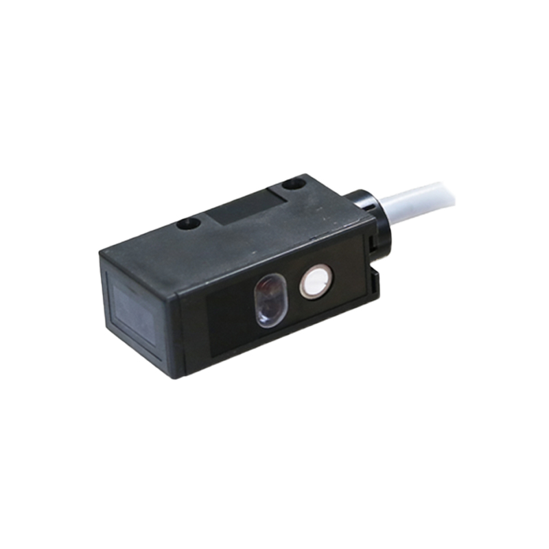
Working Principle and Signal Generation
The core operation of a photoelectric sensor in a balancing machine is based on the interruption of a light beam. A typical setup consists of an emitter, usually an infrared LED, and a receiver, such as a phototransistor or photodiode. These are mounted on opposite sides of the rotating part. A reflective or coded marker, often a piece of reflective tape or a notch on the rotor, is placed on the component being balanced. As the rotor spins, this marker passes through the sensor's detection zone. When the marker reflects (or interrupts) the light beam, the receiver detects a change in light intensity. This change is converted into an electrical pulse. This single, clean pulse per revolution serves as the key phase reference signal, telling the balancing machine's analysis system exactly when the rotor is at a known angular position. The timing of this pulse, relative to the vibration signals from the transducers, allows the system to calculate both the magnitude and the angular location of any unbalance.
Types of Photoelectric Sensors Used
Balancing machines primarily utilize two main types of photoelectric sensors: reflective and through-beam. Reflective sensors house both the emitter and receiver in a single unit. They detect the presence of a reflective marker on the rotor. This type is popular due to its simpler installation, requiring mounting on only one side of the machine. However, its performance can be susceptible to ambient light and the reflectivity of the marker and surrounding surfaces. Through-beam sensors, also called opposed-mode sensors, feature separate emitter and receiver units mounted opposite each other. They detect the interruption of the light beam by a flag or notch on the rotor. This configuration generally provides a more robust and reliable signal with higher immunity to environmental interference, making it suitable for demanding industrial environments with dust or oil mist. The choice between these types depends on factors like machine design, rotor size, required accuracy, and the operating environment.
Installation Considerations and Alignment
Proper installation and alignment are paramount for reliable photoelectric sensor performance. The sensor must be positioned so that the marker passes cleanly through its detection field at the same point in every revolution. Misalignment can lead to inconsistent or missed pulses, causing phase errors in the unbalance calculation. For reflective sensors, the angle and distance to the reflective marker must be optimized to ensure a strong return signal. The marker itself should be of high-quality reflective tape, clean, and applied smoothly to avoid creating its own minor imbalance. For through-beam sensors, precise optical alignment between the emitter and receiver is critical; even a slight misalignment can drastically reduce signal strength. Furthermore, sensors should be mounted securely to prevent vibration-induced movement, which could alter the detection point. Shielding from strong ambient light sources, such as welding arcs or direct sunlight, is also often necessary to prevent false triggering.
Common Issues and Troubleshooting
Despite their reliability, photoelectric sensors can encounter issues that affect balancing accuracy. A frequent problem is a weak or absent signal. This can be caused by a dirty lens on the sensor or emitter, a deteriorated or dirty reflective marker, misalignment, or a failed component. Intermittent signals may result from loose connections, electrical noise from nearby motors or drives, or a marker that is partially peeling off. Another issue is double-pulsing, where a single revolution generates two pulses. This can happen if the reflective marker is too large, if there is unintended reflection from another shiny surface on the rotor, or if the sensor's sensitivity is set too high. Troubleshooting typically involves a systematic approach: visually inspecting the marker and sensor cleanliness, verifying alignment, checking cable connections, and using an oscilloscope to observe the actual pulse waveform. Most modern balancing machine controllers have diagnostic functions to monitor the quality of the phase reference signal.
Integration with Balancing Machine Electronics
The pulse from the photoelectric sensor is fed into the balancing machine's electronic measurement system. Here, it undergoes conditioning. The raw signal is often converted into a clean, digital square wave with sharp rising edges. This conditioned signal serves two primary functions. First, it is used by a tachometer circuit or software algorithm to calculate the precise rotational speed (RPM), which is a critical parameter for the balancing calculation. Second, and most importantly, the rising edge of the pulse defines the zero-degree phase reference. The system correlates the vibration waveforms from the left and right plane sensors with this phase reference. By analyzing the amplitude and phase relationship, the processor can resolve the unbalance vector into its magnitude and angular position relative to the reflective marker. Advanced systems may also use this signal for triggering data acquisition windows, ensuring samples are taken at consistent points in the rotation for averaging and noise reduction.
Advancements and Future Trends
While the fundamental principle remains unchanged, advancements in photoelectric sensor technology continue to enhance balancing machine performance. Modern sensors feature improved signal-to-noise ratios, higher switching frequencies for very high-speed applications, and built-in diagnostics like LED status indicators. Some are now equipped with digital interfaces or programmable logic controller (PLC) compatible outputs. Laser-based photoelectric sensors offer extremely focused beams for detecting very small markers or for use in confined spaces. Furthermore, the integration of smart sensor technology and Industrial Internet of Things (IIoT) capabilities is emerging. Sensors with self-monitoring functions can alert operators to degrading performance or needed maintenance before they cause a faulty balance run, contributing to predictive maintenance strategies and increased overall equipment effectiveness (OEE) in manufacturing plants.