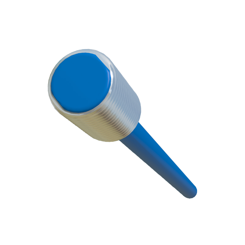
Introduction to the LM18 Inductive Proximity Switch
The LM18 represents a standard in the realm of cylindrical inductive proximity sensors, widely recognized for its reliability in industrial automation. Characterized by its 18mm diameter threaded barrel housing, this sensor is engineered for non-contact detection of metallic objects. Its core principle of operation relies on electromagnetic induction, where an oscillator generates a high-frequency electromagnetic field from the sensor's face. When a ferrous or non-ferrous metal target enters this field, eddy currents are induced, causing a change in the oscillator's amplitude. This change is detected by the internal circuitry, which subsequently triggers a solid-state switching output. The LM18's robust construction, typically featuring a nickel-plated brass or stainless-steel body, ensures exceptional resistance to mechanical stress, cutting fluids, and oils, making it a staple in harsh manufacturing environments such as CNC machining centers, automated assembly lines, and material handling systems.
Key Technical Specifications and Variants
Understanding the specifications of the LM18 sensor is crucial for proper selection and integration. The standard sensing distance for an 18mm inductive sensor is typically up to 8mm, with a guaranteed operational point (Sn) often rated at 5mm. It is vital to note that the effective sensing range can vary based on the target material; for instance, steel offers the nominal range, while aluminum or copper may reduce it significantly, often by a factor of 0.3 to 0.5. Common output configurations include NPN (sinking) and PNP (sourcing) transistor outputs in normally-open (NO) or normally-closed (NC) logic, with 3-wire or 4-wire designs. Voltage operating ranges are broad, typically from 10-30V DC, with some models supporting 20-250V AC/DC. Key performance parameters include switching frequency (often up to 1kHz), hysteresis (typically 3-10% of Sn), and protection ratings like IP67 or IP68, which guarantee resistance to dust ingress and temporary immersion. Variants may include shielded (flush-mountable) or unshielded (non-flush mountable) models, with the former allowing installation in metal without affecting the sensing field.
Installation and Wiring Best Practices
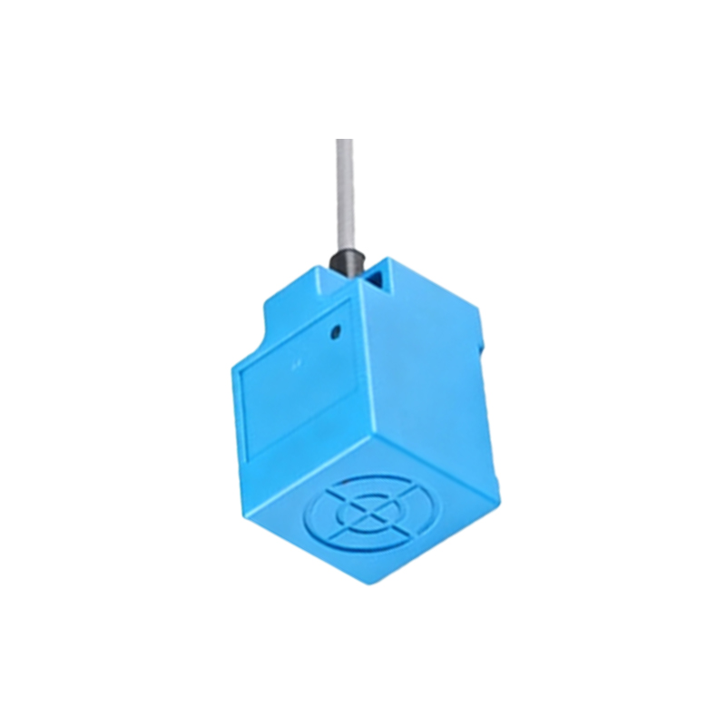
Correct installation is paramount for optimal performance and longevity of the LM18 sensor. For mounting, the standard M18x1 thread allows for easy integration into drilled and tapped holes or standard mounting brackets. When installing shielded sensors, they can be flush-mounted in metal without loss of sensing distance. Unshielded types require a non-metallic surrounding area to prevent false triggering. Adequate clearance between multiple sensors is necessary to avoid mutual interference; a general rule is to maintain a distance of at least two times the sensor diameter. Wiring must adhere strictly to the manufacturer's datasheet. For a 3-wire DC sensor, the brown wire is typically connected to the positive supply (V+), the blue wire to the negative/common (0V), and the black wire is the switched output load. The load (e.g., a PLC input, relay coil) is connected between the black wire and the opposite supply rail, depending on NPN/PNP configuration. Always ensure proper grounding and use conduit or cable glands in demanding environments to protect the connection point.
Application Scenarios and Troubleshooting
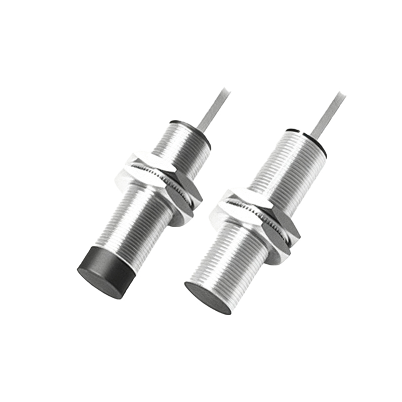
The LM18 finds extensive application across diverse industrial sectors. In automotive manufacturing, it is used for part presence verification on conveyor pallets, robot tooling confirmation, and end-of-stroke detection on actuators. In packaging machinery, it monitors the position of metallic components, counts products on metal chains, or detects fill levels in metal containers. A common use case is as a limit switch replacement, offering wear-free operation and high-speed response. Despite their robustness, issues can arise. Common troubleshooting steps include verifying power supply voltage and polarity, checking for excessive load current, and ensuring the target material and size are within specifications (the target should generally be no smaller than the sensor's sensing face). False triggers can often be traced to electrical noise in cabling; using shielded cables and separating signal lines from power lines is recommended. Physical damage to the sensing face or housing from collisions is another frequent cause of failure, underscoring the need for proper mechanical protection.
Advantages Over Mechanical Switches and Future Outlook
The advantages of the LM18 inductive proximity sensor over traditional mechanical limit switches are substantial. Its solid-state design ensures a virtually infinite operational life with no moving parts to wear out, leading to reduced maintenance downtime. It offers high