Introduction to Proximity Switch Sensors
In the realm of Computer Numerical Control (CNC) engraving machines, precision and reliability are paramount. Among the myriad components that ensure these machines operate flawlessly, proximity switch sensors play a critical, yet often understated, role. These non-contact sensors detect the presence or absence of a target object without physical contact, making them ideal for the demanding environment of CNC machining. They are essential for tasks such as homing, limit switching, and tool positioning, directly impacting the machine's accuracy, repeatability, and operational safety. Understanding their function, types, and application is crucial for any engineer or technician involved in the maintenance and optimization of engraving equipment.
Operating Principles and Key Types
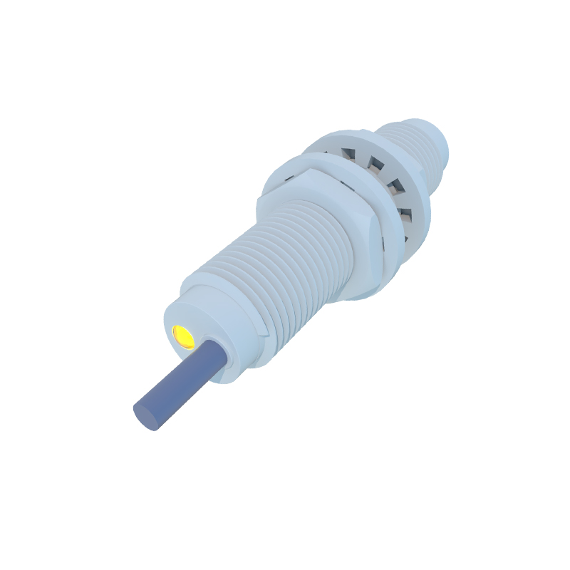
Proximity sensors operate on various physical principles. The most common types used in CNC engraving machines are inductive, capacitive, and magnetic sensors. Inductive proximity switches are the workhorses in metal machining environments. They generate an electromagnetic field and detect eddy current losses induced in metallic targets. This makes them perfect for sensing tool holders, clamps, or machine slides. Capacitive sensors, on the other hand, can detect both metallic and non-metallic materials by measuring changes in capacitance. They are sometimes used for material presence detection or liquid level sensing in auxiliary systems. Magnetic proximity sensors, often utilizing reed switches or Hall-effect sensors, are frequently employed for sensing piston positions in pneumatic systems or as simple limit switches.

Critical Roles in CNC Engraving Operations
The integration of proximity switches into an engraving machine's control system serves multiple vital functions. Primarily, they act as limit switches, preventing the machine's axes (X, Y, Z) from moving beyond their mechanical boundaries, thereby avoiding catastrophic collisions and damage. Secondly, they are used for homing sequences. At the start of a job, the machine moves each axis until the carriage triggers a home position sensor, establishing a precise and repeatable zero-reference point. This is fundamental for dimensional accuracy. Furthermore, they can be used for tool change verification, ensuring a tool is correctly seated in the spindle, or for pallet positioning in automated systems.
Selection Criteria for Optimal Performance
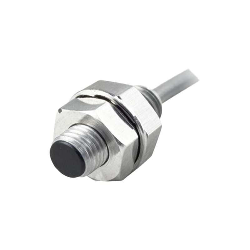
Selecting the right proximity sensor requires careful consideration of several technical parameters. Sensing distance, or the nominal range at which the sensor can reliably detect a standard target, is primary. Engineers must account for mounting constraints and required clearance. The sensor's housing material and ingress protection (IP) rating are critical for durability against coolant, oil, and metal dust prevalent in machining workshops. Output type is another key decision; PNP (sourcing) or NPN (sinking) transistors must match the CNC controller's input card specifications. Additionally, switching frequency and response time must be compatible with the machine's high-speed movements to avoid missed signals.
Installation, Alignment, and Calibration
Proper installation is non-negotiable for reliable sensor operation. The sensor must be securely mounted to resist vibration, which is inherent in engraving processes. Alignment between the sensor face and the target is crucial, especially for inductive sensors, as the sensing distance can be significantly reduced by misalignment. The air gap between the sensor and the target should be set according to the datasheet specifications, typically at 50-80% of the nominal sensing distance to ensure a stable signal margin. Calibration during machine setup involves teaching the control system the exact point of sensor activation, which becomes the reference for all subsequent movements.
Common Troubleshooting and Maintenance
Despite their robustness, proximity sensors can encounter issues. Common failures include false triggering or failure to trigger. These can stem from accumulated metallic debris on the sensor face, which can dampen the electromagnetic field. Regular cleaning with a non-abrasive cloth and isopropyl alcohol is recommended. Electrical noise from spindle drives or variable frequency drives can also interfere with sensor signals, necessitating proper shielding, grounding, and the use of twisted-pair cables. Diagnosing a faulty sensor often involves a multimeter to check output voltage or an oscilloscope to observe the signal integrity in noisy environments.
Advancements and Future Trends
The evolution of proximity sensor technology continues to enhance CNC engraving capabilities. Modern sensors are becoming smaller, allowing for more compact machine designs, while offering longer sensing distances and higher switching frequencies. IO-Link communication-enabled sensors are gaining traction, providing not just a simple on/off signal but also diagnostic data like operating temperature, signal strength, and device health directly to the CNC or PLC. This facilitates predictive maintenance, reducing unplanned downtime. Furthermore, the integration of advanced materials and coatings improves resistance to harsh coolants and extends operational lifespan.