Introduction to Photoelectric Sensor Wiring
Photoelectric sensors are indispensable components in modern industrial automation, enabling non-contact detection of objects through light beams. Among various configurations, the 5-wire photoelectric sensor is a common and versatile type, offering a balanced set of features for control and feedback. Understanding its wiring is crucial for proper installation, reliable operation, and system integration. This guide provides a detailed explanation of the 5-wire wiring diagram, focusing on standard color codes, terminal functions, and practical connection methods to ensure optimal performance in diverse applications, from conveyor systems to packaging machinery.
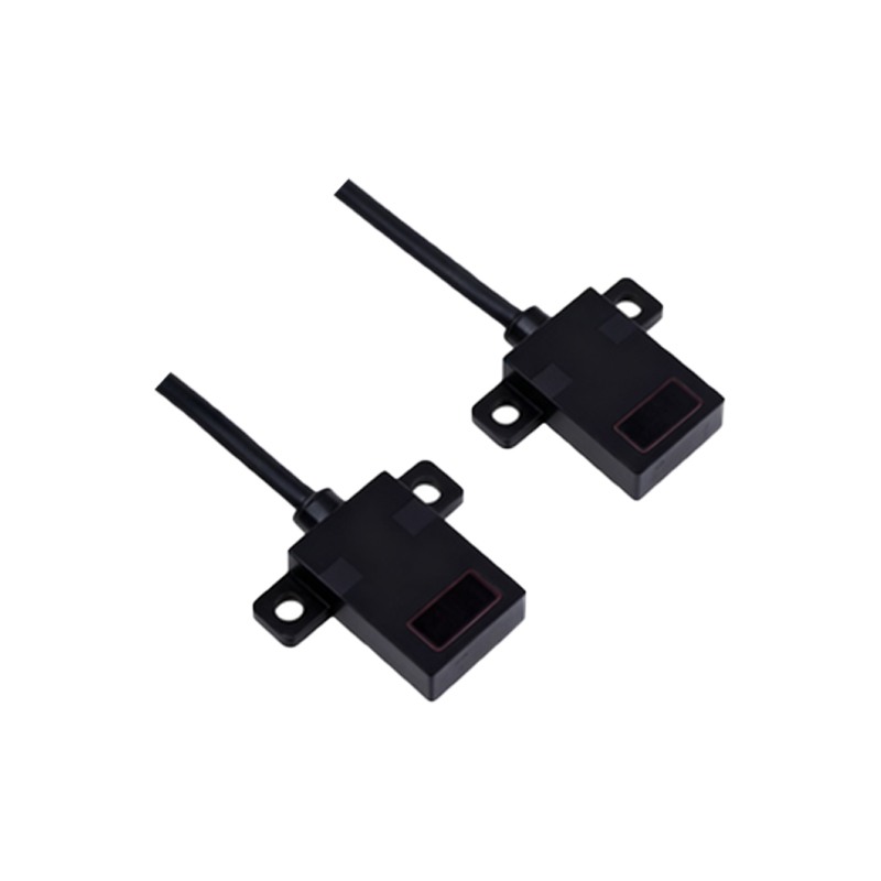
Standard Wire Color Coding and Functions
A typical 5-wire photoelectric sensor follows a conventional color scheme for its leads, though manufacturers may have slight variations. Always refer to the specific datasheet. The common configuration includes: Brown wire for the positive DC supply voltage (often +10 to +30 VDC), Blue wire for the DC common or ground (0V), Black wire for the output signal (normally open or normally closed switching output), White wire for the complementary output or control input (often used for output selection or timing functions), and a Shield or bare wire for grounding to reduce electrical noise interference. The brown and blue wires form the power circuit, while the black and white wires handle the switching logic, allowing the sensor to interface with programmable logic controllers (PLCs), relays, or other control devices.
Detailed Wiring Diagram and Connections
The wiring diagram illustrates how to connect the sensor to a power source and a load. Connect the brown wire to the positive terminal of your DC power supply. Connect the blue wire to the negative terminal of the same supply. The load (e.g., the input of a PLC, a relay coil, or an indicator lamp) is connected in series with the sensor's output. For the black wire (output), one side connects to the positive supply (via the load), and the other side is internally switched to the blue wire (common) when active. The white wire's function depends on the sensor mode; it might be connected to the blue wire to select a light-on/dark-on operation or left unconnected. The shield wire should be grounded at the control panel to the earth ground terminal for optimal electromagnetic compatibility (EMC).
Output Types and Configuration Modes
Five-wire sensors typically feature a relay or solid-state output with complementary logic. The black wire usually provides the main NPN (sinking) or PNP (sourcing) transistor output. The white wire often serves as a second, complementary output or a mode selector. For instance, in some models, connecting the white wire to the blue wire sets the output to operate in "dark-on" mode (output activates when the light beam is blocked), while leaving it open sets "light-on" mode (output activates when the beam is received). This flexibility allows users to configure the sensor's behavior without internal adjustments, simplifying setup for different sensing requirements, such as detecting transparent objects or contrasting backgrounds.
Practical Installation and Troubleshooting Tips
Correct installation ensures long-term reliability. Use twisted-pair cables for the brown and blue power wires to minimize voltage drop. Keep output wires (black/white) separate from high-voltage AC lines to prevent inductive noise. Secure all connections with appropriate terminals and ensure the shield is grounded only at one end to avoid ground loops. For troubleshooting, if the sensor fails to operate, first verify power (brown/blue) with a multimeter. Check the output (black wire) for voltage switching when an object interrupts the beam. Inspect the white wire connection if the output logic seems inverted. Always ensure the sensing range and environment (dust, moisture) are within the sensor's specifications, as external factors can affect performance.
Integration with Control Systems
Integrating a 5-wire photoelectric sensor into a control system like a PLC is straightforward. The black output wire connects to a digital input card on the PLC. For a PNP sensor, the black wire provides positive voltage to the PLC input when active, and the PLC input's common is connected to ground. For an NPN sensor, the black wire sinks current to ground. The white wire can be used for advanced functions, such as connecting to another PLC input to monitor sensor status or to a digital output to remotely toggle modes. This dual-wire output capability enhances system diagnostics and flexibility, allowing for more complex automation sequences and fail-safe monitoring in applications like robotic assembly or material handling.
Conclusion and Best Practices
Mastering the 5-wire photoelectric sensor wiring is essential for efficient automation design. By adhering to standard color codes, understanding output configurations, and following proper installation guidelines, engineers can ensure robust sensor performance. Always consult the manufacturer's documentation for model-specific details, as features like short-circuit protection or timed outputs may influence wiring. Regular maintenance, including lens cleaning and connection checks, further extends sensor life. Embracing these practices not only optimizes individual sensor functionality but also contributes to the overall reliability and productivity of industrial automation systems, making the 5-wire photoelectric sensor a reliable choice for precise object detection.