Understanding Proximity Sensor Indicator Lights
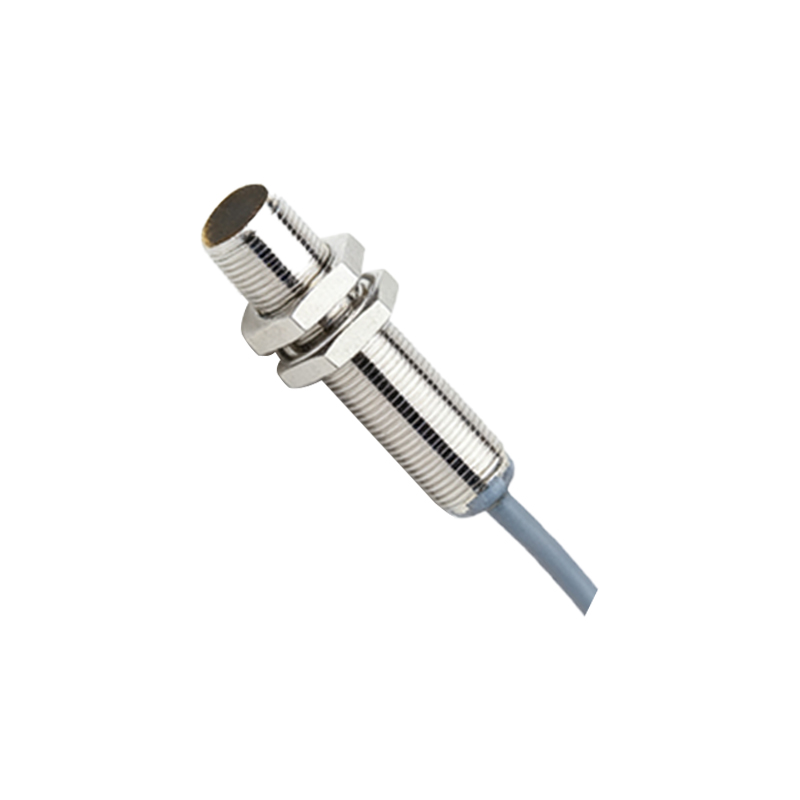
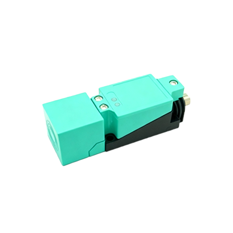
Proximity sensors are widely used in industrial automation for detecting the presence or absence of objects without physical contact. Most modern proximity sensors feature an LED indicator light, typically labeled as "output" or "status." This light is designed to provide a visual confirmation of the sensor's operational state. When an object enters the sensing range, the sensor activates its output, and the LED illuminates. Conversely, when no object is detected, the light remains off. This simple visual cue aids in quick troubleshooting and setup during installation. However, interpreting this light as a definitive sign of sensor health can be misleading. The illumination merely indicates that the sensor's internal switching mechanism has been triggered, but it does not guarantee that the signal is being correctly transmitted to the control system or that the sensor is functioning within its specified parameters.
Common Misconceptions About LED Indicators
A prevalent misconception among technicians and operators is that a lit proximity sensor light always signifies proper operation. In reality, several issues can cause the LED to light up even when the sensor is malfunctioning. For instance, electrical noise or interference in the environment can induce false triggering, causing the indicator to illuminate without an actual target present. Additionally, sensor wear or contamination—such as buildup of metal shavings, oil, or dust on the sensing face—can alter the sensing characteristics. This may lead to reduced sensing distance or erratic behavior, where the light turns on intermittently or at incorrect times. Another scenario involves wiring faults; a short circuit in the output wiring might keep the LED constantly lit, even if the sensor's internal electronics are damaged. Therefore, relying solely on the indicator light for diagnostics can result in overlooked problems and unplanned downtime.
Factors That Affect Sensor Performance
To accurately assess a proximity sensor's condition, one must consider multiple performance factors beyond the LED. Sensing distance is critical; over time, components can degrade, causing the effective range to diminish. Even if the light activates, the sensor might not detect objects at the specified distance, leading to process errors. Response time is another key parameter; a slow-responding sensor may light up but fail to keep up with high-speed automation cycles, causing missed detections. Environmental conditions also play a significant role. Extreme temperatures, humidity, or exposure to corrosive substances can impair sensor functionality. For example, in high-temperature settings, the LED might light up, but the sensor could be operating outside its thermal limits, risking premature failure. Regular calibration and testing with known targets are essential to verify that the sensor meets its datasheet specifications, rather than depending on the indicator alone.
Diagnostic Steps Beyond the Indicator Light
Effective troubleshooting requires a systematic approach that goes beyond observing the LED. First, verify the power supply to ensure it matches the sensor's voltage requirements—both under-voltage and over-voltage can cause erratic indicator behavior. Next, use a multimeter or oscilloscope to measure the output signal directly at the sensor's terminals. This confirms whether the electrical signal corresponds to the LED state. For instance, a lit LED with no output voltage suggests internal damage. Additionally, inspect the physical installation: ensure the sensor is properly aligned, free from obstructions, and mounted securely. Vibration or misalignment can cause intermittent operation. Testing with a calibration target at varying distances helps evaluate sensing consistency. Many advanced sensors also offer diagnostic features via IO-Link or other communication protocols, providing detailed status information like temperature warnings or contamination alerts, which the LED alone cannot convey.
Best Practices for Maintenance and Reliability
To maximize proximity sensor reliability, implement proactive maintenance routines. Schedule periodic inspections to clean sensing surfaces and check for environmental damage. Use shielded cables and proper grounding to minimize electrical interference that might affect the indicator. Document sensor performance over time, noting any changes in behavior compared to baseline readings. When replacing sensors, choose models with robust diagnostics, such as those with dual LED indicators (e.g., one for power and one for output) or smart sensors that communicate health data to control systems. Training personnel to understand sensor specifications and limitations is crucial; they should know that a lit LED is just one piece of the puzzle. By combining visual checks with electrical measurements and environmental monitoring, teams can prevent failures and maintain efficient operations, ensuring that "light on" truly means "all systems go."