Introduction to Proximity Sensor Mechanics
Proximity sensors are fundamental components in modern automation, serving as the critical "eyes" of machinery by detecting the presence or absence of objects without physical contact. Their reliability and precision hinge not just on sophisticated electronics but equally on a robust and well-designed mechanical structure. This mechanical framework protects sensitive internal components from harsh industrial environments—including dust, coolant, metal chips, vibration, and electromagnetic interference—while ensuring optimal sensing performance. Understanding the mechanical diagram of a proximity sensor is essential for engineers to select, install, and maintain these devices effectively. The housing, sensing face, internal coil assembly, and connection elements all work in concert to deliver a signal that drives control logic. A failure in the mechanical integrity can lead to false triggers, reduced sensing range, or complete device failure, underscoring the importance of its design.
External Housing and Material Composition
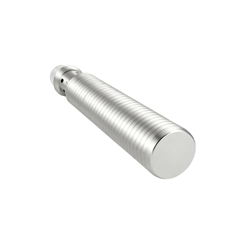
The first and most visible part of the mechanical structure is the external housing or body. Typically fabricated from materials like nickel-plated brass, stainless steel (e.g., 303, 304, or 316 grades), or high-grade engineering plastics such as PBT or PPS, the housing provides the primary defense. Metal housings offer superior resistance to physical impact, crushing forces, and high temperatures, making them ideal for heavy-duty machining or forging applications. Plastic housings are used where cost sensitivity or non-metallic detection environments are priorities. The housing is not a simple tube; its geometry is carefully calculated. The front section, or sensing face, is often a flat or slightly curved surface made from a specific material (like PTFE or ceramic in weld-field immune models) that allows the electromagnetic field or ultrasonic waves to pass through with minimal attenuation. The body is typically threaded (e.g., M8, M12, M18, M30 metric threads) for secure mounting into a drilled and tapped hole, featuring hex flats for wrench tightening and often an integrated mounting nut.
Internal Core Assembly and Sensing Element
Encapsulated within the protective housing lies the heart of the sensor: the internal core assembly. For an inductive proximity sensor, the core component is a ferrite core surrounded by a precisely wound copper coil, which forms part of an oscillator circuit. This assembly is potted or encapsulated in a resilient epoxy resin compound. This potting serves multiple mechanical functions: it permanently secures the coil and core in perfect alignment, provides exceptional resistance to shock and vibration that could break fine wire windings, and creates a hermetic seal against moisture and chemical ingress. The potting material's dielectric properties are crucial as they affect the sensor's field characteristics. In capacitive sensors, the sensing element comprises conductive plates, while in ultrasonic sensors, it involves a piezoelectric transducer. All these delicate elements are similarly protected by potting and strategically positioned behind the sensing face at a fixed, non-adjustable distance that defines the sensor's nominal sensing range.
Connection and Cable Strain Relief
The rear of the sensor houses the electrical connection system, a critical mechanical interface. Sensors come in two main styles: pre-wired (with an attached cable) or connector versions. For pre-wired models, the cable enters the housing through a robust strain relief gland. This gland is a masterpiece of mechanical design, often comprising a compression nut, a sealing ring, and a collet that grips the cable jacket. Its purpose is to absorb any pulling, twisting, or bending forces applied to the cable, preventing these stresses from being transferred to the internal solder joints or PCB connections, which would lead to wire breakage. Inside, the cable conductors are soldered or screw-clamped to a terminal block or a small printed circuit board (PCB). Connector-style sensors feature a standardized threaded or quick-disconnect connector (e.g., M12, M8 coded connectors), which includes sealing O-rings to maintain the IP (Ingress Protection) rating. The internal seal between the connector insert and the sensor body is vital for achieving ratings like IP67 or IP69K.
Shielding and Field Focusing Geometry
A key mechanical feature, especially in inductive sensors, is the shielding. Shielded (or flush-mountable) sensors have a metallic band (often part of the front housing) that surrounds the sensing face. This band focuses the electromagnetic field radially forward from the face. This mechanical design allows the sensor to be installed flush with a metal mounting bracket without the bracket itself being detected, preventing false triggers. Unshielded (non-flush mountable) sensors lack this front metal band, resulting in a larger, more diffuse field that extends laterally. Their mechanical structure requires them to be installed with a clearance from surrounding metals as specified by the manufacturer. The shape and thickness of this shielding are precisely engineered to balance sensing range