Introduction to Sunlight Photoelectric Sensors
Sunlight photoelectric sensors are critical components in modern industrial automation, designed to detect the presence, absence, or distance of objects using light beams. Unlike standard photoelectric sensors, these devices are specifically engineered to operate reliably under intense ambient light conditions, such as direct sunlight or high-intensity artificial lighting. Their robust construction and advanced filtering technologies allow them to distinguish between the modulated light signal they emit and external light interference. This capability makes them indispensable in outdoor applications, solar panel tracking systems, and brightly lit manufacturing environments where false triggers must be minimized. Understanding their operational principle is the first step toward correct installation and wiring.
Key Wiring Components and Specifications
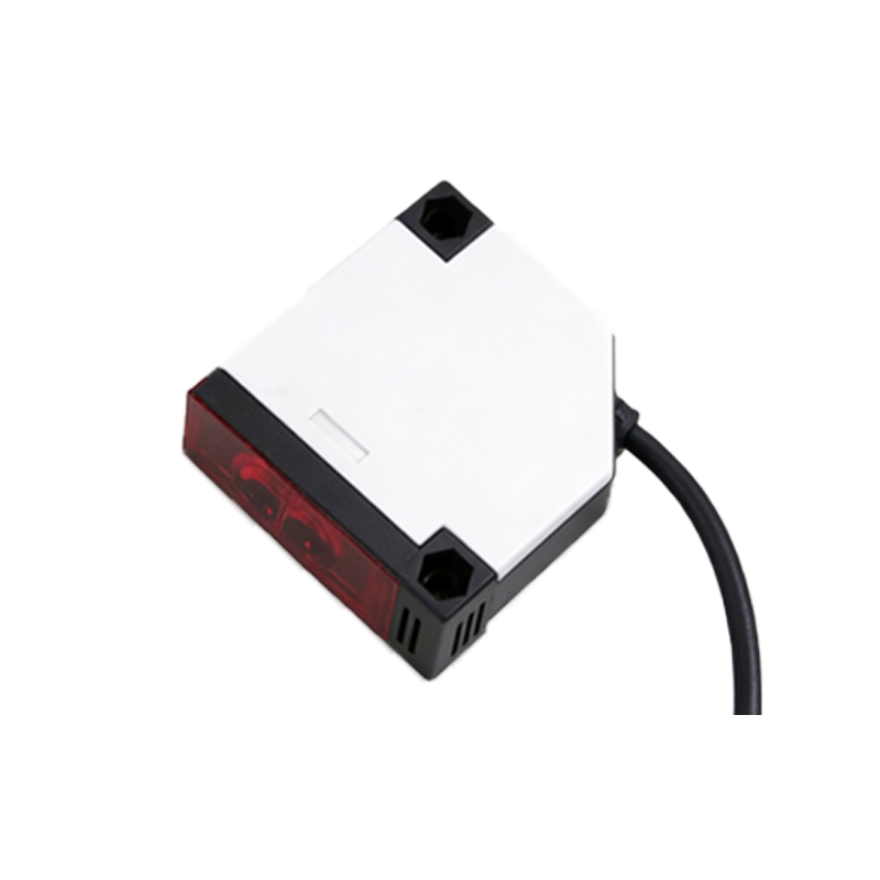
Before commencing any wiring procedure, it is essential to identify all necessary components and review the sensor's datasheet. A typical sunlight photoelectric sensor unit includes a sensor head, a cable or connector interface, and sometimes a separate amplifier or controller. The core electrical specifications to verify are the operating voltage (commonly 12-24V DC for industrial models), output type (e.g., NPN, PNP, or relay), and current rating. Additionally, note the light source type (often infrared or laser) and the sensing mode (through-beam, retro-reflective, or diffuse). Always ensure that the power supply matches the sensor's voltage requirements and has adequate current capacity. Using shielded cables is highly recommended to protect against electromagnetic interference, especially in environments with heavy machinery or variable frequency drives.
Step-by-Step Wiring Procedure
Begin by disconnecting all power sources to prevent electrical shock or equipment damage. Mount the sensor securely in its intended location, ensuring proper alignment for optimal performance. For a standard three-wire DC sensor, connect the brown wire (typically positive) to the positive terminal of your DC power supply. Connect the blue wire (typically negative or common) to the negative terminal. The output wire (often black or white) should be connected to the load, such as a programmable logic controller (PLC) input, relay coil, or indicator light. If the sensor features a teach-in function or diagnostic outputs, refer to the manual for additional wiring details. For four-wire models with both NPN and PNP outputs, carefully follow the pinout diagram. After connections are made, double-check all terminals for tightness and correct polarity.
Shielding and Grounding Best Practices
Proper shielding and grounding are paramount for stable sensor operation, particularly in industrial settings with significant electrical noise. Use cables with braided or foil shields, and connect the shield drain wire to a clean earth ground at the control panel end only, avoiding ground loops. The grounding point should have low impedance and be separate from high-power equipment grounds. If the sensor is installed in a metallic enclosure, ensure the enclosure itself is grounded. For long cable runs exceeding the manufacturer's recommended length (often 100 meters), consider using signal conditioners or repeaters to maintain signal integrity. Additionally, route sensor cables away from power lines, motor drives, and other sources of electromagnetic interference to minimize inductive coupling.
Configuration and Alignment Techniques
After wiring, apply power and proceed with configuration. Many sunlight photoelectric sensors feature sensitivity adjustments, response time settings, and output logic selection (light-on/dark-on). Use a small screwdriver or built-in buttons to set the sensitivity threshold so that the sensor reliably detects the target while ignoring background light variations. For through-beam types, align the emitter and receiver precisely; a laser alignment tool can be invaluable for long-range setups. Retro-reflective sensors require proper alignment with their reflector, and diffuse sensors need careful consideration of the target's reflectivity and distance. Always perform testing with the actual target object under normal operating lighting conditions to validate the settings.
Troubleshooting Common Wiring Issues
If the sensor fails to operate as expected, methodically check the wiring connections first. Verify power supply voltage with a multimeter at the sensor terminals. Ensure the load is compatible and functional—for instance, test by temporarily substituting a known-good indicator. If the sensor outputs erratically, inspect for loose connections, damaged cables, or insufficient shielding. Ambient light overload can sometimes still occur; consider installing a sunshade or tube around the sensor head. Consult the sensor's diagnostic LEDs, which typically indicate power status, output activation, and stability. Persistent issues may require consulting the manufacturer's troubleshooting guide or verifying that the sensor model is suitable for the specific environmental and application demands.
Maintenance and Safety Considerations
Regular maintenance ensures long-term reliability. Periodically inspect cables for wear, corrosion, or physical damage. Clean the sensor lens with a soft, lint-free cloth to remove dust, oil, or debris that could attenuate the light beam. Avoid using harsh chemicals. Check mounting hardware for tightness, as vibration can loosen connections over time. From a safety perspective, always lock out and tag out power sources before performing any maintenance or wiring modifications. Adhere to all local and international electrical codes, such as NEC, IEC, or ISO standards. For complex systems, maintain updated wiring diagrams and sensor documentation to facilitate future troubleshooting or expansion.