Understanding Proximity Sensor Fundamentals
Proximity sensors are non-contact devices used to detect the presence or absence of an object within a defined sensing range. They are fundamental components in industrial automation, robotics, and safety systems. The most common types include inductive sensors for detecting metallic objects, capacitive sensors for detecting both metallic and non-metallic materials, and photoelectric sensors using light beams. Each type operates on a different physical principle but shares a common goal: providing a reliable electrical signal based on target detection. Before wiring, it is crucial to identify the sensor type, its operating voltage (commonly 10-30V DC or 90-250V AC), output configuration (PNP-sourcing or NPN-sinking for DC; NO-Normally Open or NC-Normally Closed contacts for relays), and the specific requirements of the load it will control, such as a PLC input, relay coil, or indicator lamp. Always consult the manufacturer's datasheet for the exact specifications and wiring diagrams pertinent to your model.
Essential Tools and Safety Precautions
Proper installation begins with gathering the right tools and adhering to strict safety protocols. You will typically need wire strippers, crimping tools, appropriate screwdrivers, a multimeter for voltage and continuity checks, and the correct gauge of shielded cable, often recommended to minimize electrical noise interference in industrial environments. The paramount rule is to ensure all power sources to the circuit and machinery are locked out and tagged out (LOTO) before starting any wiring work. Verify that the supply voltage matches the sensor's rated voltage precisely. Using an incorrect power supply can lead to immediate sensor failure or erratic operation. Wear appropriate personal protective equipment (PPE), and ensure your work area is clean, dry, and well-lit. Remember, even low-voltage DC circuits can be connected to higher-voltage control systems; assume all connections are hazardous until proven otherwise.
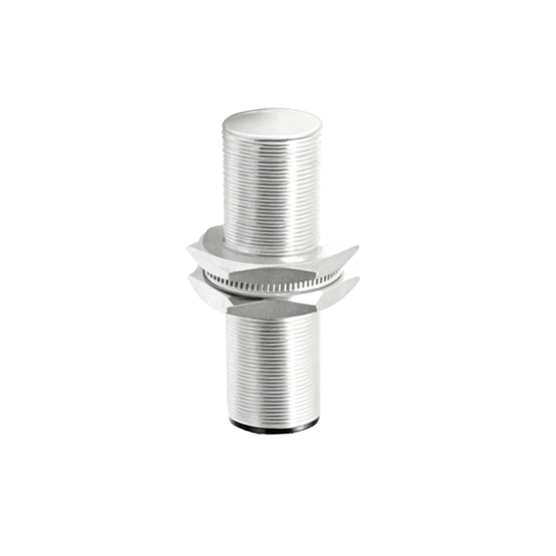
Wiring a 3-Wire DC Proximity Sensor
The 3-wire DC sensor is the most prevalent configuration in modern industrial panels. These sensors have three distinct wires: brown for positive supply voltage (+V), blue for common negative (0V), and black for the switched output signal. For a PNP (sourcing) sensor, the internal switching element connects the black output wire to the positive supply when a target is detected. To wire it, connect the brown wire to the positive terminal of your DC power supply (e.g., +24V). Connect the blue wire to the negative terminal (0V) of the same supply. The black output wire is then connected to the load (e.g., one side of a PLC digital input module). The other side of the PLC input must be connected to the power supply's negative (0V). This completes the circuit, allowing current to source from the sensor to the PLC when activated. For an NPN (sinking) sensor, the black wire connects the load to negative when active. Here, the load must be connected between the positive supply and the black wire. The blue wire still goes to negative, and the brown to positive. The load's other terminal connects to positive. Always use the correct polarity; reversing brown and blue will damage the sensor.
Wiring a 2-Wire DC or AC Sensor
Two-wire sensors are simpler, acting like a switch in series with the power line. They have only two wires, typically brown and blue. These sensors can be used with both AC and DC supplies, but you must select a model rated for your specific supply voltage. Wiring is straightforward: one wire (brown) is connected to the positive (for DC) or phase/live (for AC) side of the power supply. The other wire (blue) is connected to one terminal of the load. The remaining terminal of the load is then connected back to the negative (for DC) or neutral (for AC) side of the power supply, completing the series loop. A crucial consideration with 2-wire sensors is the leakage current. Even in the "off" state, a small current flows through the sensor. The load must have a low enough impedance to prevent this leakage current from inadvertently activating it. If controlling a high-impedance PLC input, a bleeder resistor may be required across the load to ensure proper off-state signal.
Connecting to Programmable Logic Controllers (PLCs)
Integrating a proximity sensor with a PLC is a common task. The key is to match the sensor's output type with the PLC input type. Most PLC digital input modules are designed to work with either sinking (NPN) or sourcing (