What is Proximity Sensor Polarity?
In the realm of industrial automation and electrical control systems, the term "proximity sensor polarity" refers to the electrical characteristic that defines the type of output signal a sensor provides in relation to its power supply connections. Fundamentally, it specifies whether the sensor's output switch connects the load to the positive voltage line (sourcing, or PNP) or to the ground/negative line (sinking, or NPN). This is a critical specification that determines how the sensor integrates into a control circuit. Misunderstanding or mismatching polarity is a common source of installation errors, leading to sensor malfunction or damage to connected controllers like PLCs (Programmable Logic Controllers). The concept is analogous to the polarity of a DC power supply or a semiconductor; correct orientation is essential for current to flow as intended.
PNP (Sourcing) Output Configuration
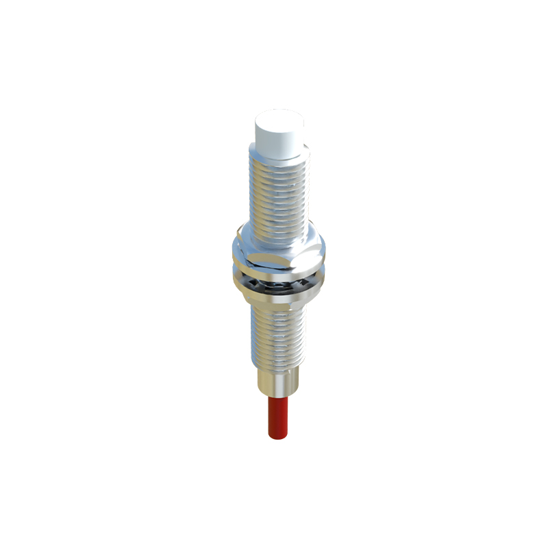
A PNP proximity sensor is characterized by its sourcing output. In this configuration, the sensor's internal switching element (typically a transistor) is connected between the positive supply voltage and the output wire. When the sensor is inactive (no target detected), the output is in a high-impedance state, effectively disconnected. Upon detecting a target within its sensing range, the internal switch closes, connecting the output terminal to the positive supply voltage. This "sources" current from the sensor's output to the load. The load (e.g., a PLC input module, relay coil, or indicator lamp) must then be connected between this output and the common negative (0V) line. PNP sensors are often described as having a "positive switching" logic and are the standard convention in many European and Asian control system designs.
NPN (Sinking) Output Configuration
Conversely, an NPN proximity sensor features a sinking output. Here, the internal switching element is connected between the output wire and the common negative or ground line. When inactive, the output is again in a high-impedance state. When activated by a target, the switch closes, connecting the output terminal to the ground. This "sinks" current from the load into the sensor. In this setup, the load must be connected between the positive supply voltage and the sensor's output terminal. The current flows from the positive supply, through the load, and into the sensor's output, which then sinks it to ground. NPN sensors are termed "negative switching" and are commonly used in Japanese and North American control system traditions. Understanding this distinction is paramount for circuit design.
Key Differences and Wiring Diagrams
The core difference lies in the current path and the required load connection. For a PNP sensor, the load is wired to the negative common; for an NPN sensor, the load is wired to the positive supply. A simple mnemonic is "PNP: Positive-switched, Positive to load." In a typical 3-wire DC sensor (Brown wire to +V, Blue wire to 0V, Black wire as output), the wiring changes based on polarity. With a PNP sensor, the PLC input connects between Black (output) and Blue (0V). With an NPN sensor, the PLC input connects between Brown (+V) and Black (output). Many modern PLC input modules are designed to be universal, accepting either PNP or NPN signals by configuring their common terminal as either positive or negative, but the sensor and load wiring must be consistent.
Selecting the Correct Polarity for Your Application
Choosing between PNP and NPN is not a matter of performance but of system compatibility. The decision is primarily dictated by the input characteristics of the controller receiving the signal. First, consult the controller's (PLC, relay module, counter) manual to determine whether it requires a sourcing (PNP) or sinking (NPN) input. Second, consider the prevailing standard in your facility or region to maintain consistency across machinery. Third, in complex systems with mixed logic, interface relays or opto-isolators can be used to convert between polarities. A critical safety note: never directly connect a PNP sensor output to an NPN sensor output or vice versa on a shared line, as this can create a short circuit across the power supply.
Troubleshooting Common Polarity Issues
A sensor that fails to trigger a PLC input is often a polarity mismatch. Symptoms include the PLC input LED not illuminating despite the sensor's indicator LED turning on. To diagnose, first verify the sensor's polarity marking (PNP or NPN) on its housing or datasheet. Then, check the wiring against the correct diagram. Use a multimeter to measure the voltage between the sensor's output wire and the common (Blue