Understanding the Core Components
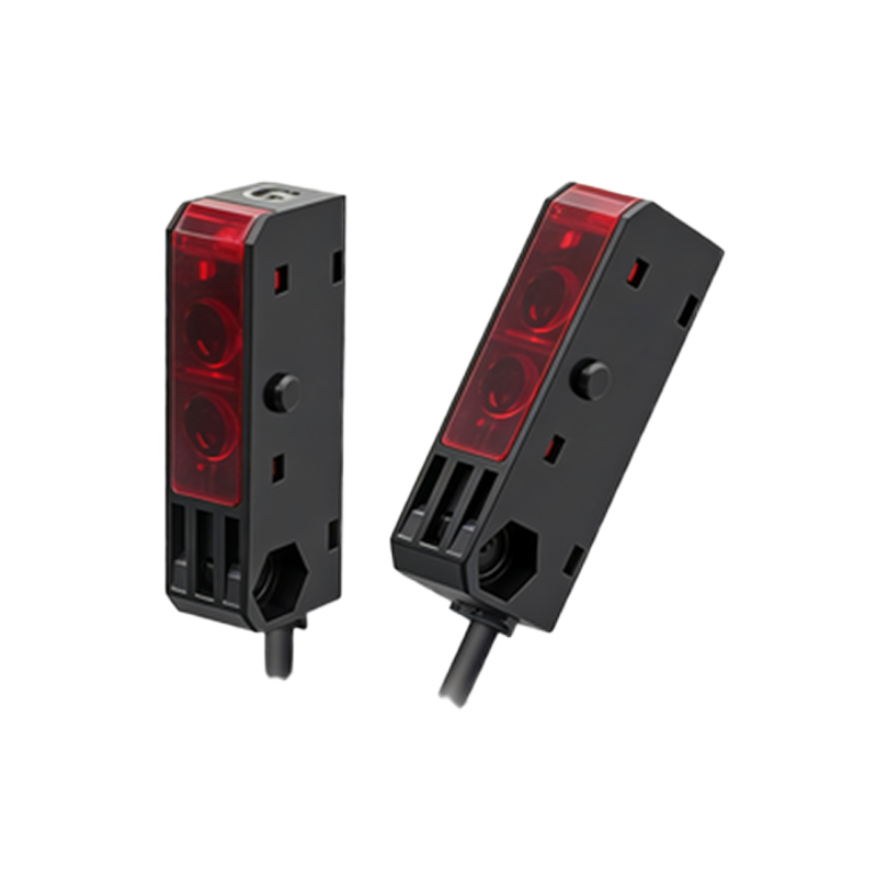
Before putting pen to paper or cursor to CAD software, a thorough understanding of the photoelectric sensor's internal architecture is paramount. A typical through-beam or retro-reflective sensor comprises several key sub-assemblies. The core is the emitter block, housing the light source (often an LED or laser diode), its associated driver circuitry, and a precision lens. Opposite or adjacent is the receiver block, containing the photodetector (such as a phototransistor or photodiode), signal amplification electronics, and another lens. These are encased within a housing, which includes mounting features like threads, brackets, or slots. Additional components may include adjustment potentiometers, status indicator LEDs, cable glands, and connector interfaces. Creating a detailed bill of materials (BOM) for these parts is the foundational first step for any accurate assembly drawing.
Establishing Drawing Standards and Views

Adherence to recognized international drafting standards, such as ASME Y14.5 or ISO 128, is non-negotiable for professional documentation. Begin by defining your sheet format, including title block information (part number, sensor model, revision, company details). The primary view should be a full-section view, cutting through the central axis of the sensor. This is the most critical view as it reveals the spatial relationship between the internal emitter, receiver, PCBAs, and the external housing. Complement this with orthogonal views (top, front, side) to show external contours, mounting dimensions, and port locations. An exploded isometric view is highly recommended to illustrate the assembly sequence and component identification clearly. All views must be properly aligned and scaled.
Detailing Component Geometry and Relationships
In the section view, meticulously detail each component. The housing should be shown with its wall thickness, internal cavities, and sealing features. The emitter and receiver lenses must be drawn with their curvature and precise location relative to the light source and detector. The printed circuit board assemblies (PCBAs) should be depicted with their outline, major components (chips, resistors), and connector footprints. Use different line weights and shading/hatching patterns to distinguish between different materials (e.g., plastic housing, metal threads, glass lenses, silicon PCBs). Critical interfaces, such as how the lens is seated in a bezel or how the PCBA is secured with screws or snap-fits, must be clearly depicted. Centerlines for optical axes are essential.
Applying Dimensions, Tolerances, and Annotations
Dimensions drive manufacturing. Focus on critical functional dimensions: the exact distance between the emitter and receiver optical axes (for opposed models), the focal point or sensing range, mounting hole patterns, thread specifications, and overall enclosure dimensions. Apply geometric dimensioning and tolerancing (GD&T) where necessary, such as positional tolerances for mounting holes or perpendicularity of the mounting surface to the optical axis. Annotate all components with balloon callouts keyed to your BOM. Include notes for assembly instructions: "Apply thread-locking adhesive to housing screws," "Ensure O-ring is seated in groove before final assembly," or "Calibrate potentiometer P1 after sealing." Specify any special assembly torques.
Incorporating Electrical and Interface Information
While primarily mechanical, an assembly drawing for an electro-optical device must reference its electrical interfaces. This can be done through detailed callouts on the drawing or by referencing separate wiring diagrams. Indicate the cable entry point, strain relief, and the pin-out of the connector (e.g., Pin 1: Vcc, Pin 2: Output, Pin 3: GND). If the housing has a wiring chamber, show it. For sensors with adjustment potentiometers, label them (e.g., "Sensitivity Adj.") and indicate their rotational direction for adjustment. This integration ensures the mechanical assembly team understands the context of the parts they are handling.
Finalizing with BOM and Revision Control
A complete assembly drawing package includes a detailed Bill of Materials table. List every item, from the main housing down to the smallest screw and O-ring. For each item, provide the item number (matching balloon callouts), part number, description, material, and quantity per assembly. The title block must manage revision history. Each time a component is changed (e.g., a lens supplier is updated), the drawing must be revised, and the change documented. This controls the configuration and ensures anyone, from assembly to service, is working from the correct documentation. Finally, perform a thorough check: verify all dimensions are unambiguous, all parts are listed, and the drawing clearly communicates how the sensor is physically put together.