Introduction to the Nova65G Proximity Light Sensor
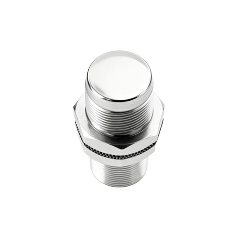
The Nova65G proximity light sensor represents a significant advancement in optoelectronic components, designed for high-precision detection in various industrial and consumer applications. This sensor integrates an infrared emitter and a photodetector in a compact surface-mount package, enabling reliable non-contact detection of objects within a specified range. Its core function is to emit an infrared light beam and measure the intensity of the reflected light to determine the presence or absence of a target object. The "65G" designation often refers to specific performance characteristics, such as its sensing distance or package type, which engineers must verify against the official datasheet for their particular model variant. Understanding its fundamental operating principle is the first step toward effective implementation.
Key Electrical Specifications and Pin Configuration
Before integrating the Nova65G into any circuit, a thorough review of its electrical specifications is paramount. Typical operating parameters include a supply voltage range of 2.5V to 3.6V, making it suitable for low-power embedded systems. The quiescent current is usually in the microampere range, while the active sensing current may peak during IR emission pulses. The sensor's output is commonly a digital signal that toggles based on the detected reflection threshold. The standard pin configuration for such a package includes VCC (power supply), GND (ground), SCL/SDA (for I2C communication models), and INT (interrupt output). Some variants may offer an analog output pin. Always cross-reference the pinout diagram in the manufacturer's datasheet to avoid connection errors that could damage the component.
Circuit Design and Integration Principles
Successful deployment of the Nova65G requires careful circuit design. Power supply decoupling is critical; place a 0.1µF ceramic capacitor as close as possible to the VCC and GND pins to filter high-frequency noise. If the sensor uses I2C protocol, ensure pull-up resistors (typically 4.7kΩ) are present on the SCL and SDA lines. For models with an interrupt output, this line can be connected directly to a microcontroller's GPIO pin configured for interrupt-on-change functionality, enabling efficient, event-driven system response. The sensor should be positioned on the PCB to ensure its IR lens has an unobstructed path to the detection area. Avoid placing tall components or connectors that could cast shadows or cause false reflections near the sensor's field of view.
Microcontroller Interfacing and Communication Protocol
Interfacing the Nova65G with a microcontroller, such as an ARM Cortex-M or popular ESP32, involves both hardware connection and software configuration. For I2C-based models, initialize the microcontroller's I2C peripheral at a standard speed (e.g., 100kHz or 400kHz). The first software task is to verify communication by reading the device's WHO_AM_I or similar register address. Subsequently, engineers must configure the sensor's operational registers. Key settings include setting the proximity detection threshold, adjusting the IR LED pulse current and duration for the desired sensing range, and configuring the interrupt generation logic (e.g., trigger when an object is closer than the threshold). Many manufacturers provide driver libraries or example code to expedite this process.
Calibration and Threshold Adjustment Procedures
Calibration is essential to adapt the Nova65G's sensitivity to the specific mechanical and environmental conditions of the final product. The process typically involves placing a standard reflective target at the desired detection distance and reading the raw proximity data output. This value is then used to set the detection threshold in the corresponding register. Factors like the color, material, and reflectivity of the target object, as well as ambient infrared light (from sunlight or incandescent bulbs), can affect readings. Some advanced sensors feature automatic calibration routines or ambient light subtraction algorithms. Engineers should design a calibration mode into their firmware, allowing for threshold adjustment during production testing or field maintenance.
Software Implementation and Algorithm Considerations
Robust software goes beyond simple register configuration. Implement a debouncing algorithm in firmware to filter out transient detections caused by fast-moving objects or electrical noise. This can be a simple counter that requires several consecutive positive readings before confirming an object's presence. For applications requiring distance estimation rather than binary detection, engineers can develop a lookup table or a linear interpolation model that maps the raw ADC values from the sensor to approximate distances in millimeters. Furthermore, implementing a periodic sensor health check, such as verifying the internal oscillator is functional, can enhance system reliability. Always ensure the main application loop or RTOS task does not block the timely reading of the sensor's interrupt signal.