Introduction to M3 Proximity Sensors
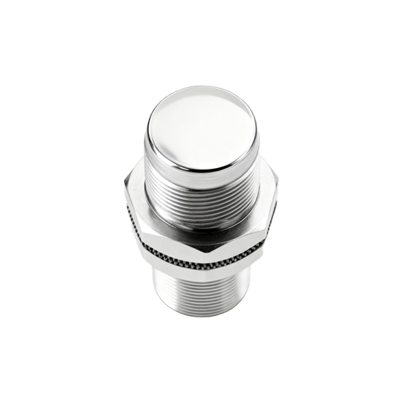
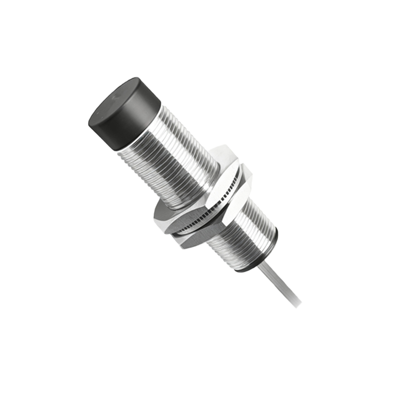
M3 proximity sensors are widely utilized in industrial automation and machinery for non-contact detection of metallic objects. These compact devices, typically housed in an M3 threaded cylindrical body, offer reliable performance in harsh environments. They operate based on electromagnetic principles, enabling precise sensing without physical contact, which minimizes wear and tear. Commonly applied in manufacturing lines, robotics, and safety systems, M3 sensors contribute to enhanced efficiency and reduced maintenance costs. Their small size allows for easy integration into tight spaces, making them a versatile choice for various engineering applications.
Core Operating Principle
The fundamental working principle of M3 proximity sensors revolves around electromagnetic induction. Inside the sensor, an oscillator generates a high-frequency alternating magnetic field at the sensing face. When a metallic target, such as steel or aluminum, enters this field, eddy currents are induced on the target's surface. These currents absorb energy from the oscillator, causing a reduction in oscillation amplitude. The sensor's detection circuit monitors this change and triggers an output signal—typically a switch to ON or OFF state—when the amplitude drops below a predefined threshold. This process occurs rapidly, ensuring real-time response to object presence.
Key Components and Design
An M3 proximity sensor comprises several critical components: a coil wound around a ferrite core, an oscillator circuit, a demodulator, and an output switching element. The coil and core generate the magnetic field, while the oscillator sustains the frequency. The demodulator converts amplitude changes into a usable signal, and the output element, often a transistor or relay, controls external circuits. The M3 housing, usually made of stainless steel or nickel-plated brass, provides durability against moisture, dust, and mechanical impacts. This robust design ensures consistent operation in temperatures ranging from -25°C to 70°C, with IP67 or higher ingress protection ratings.
Types and Sensing Ranges
M3 proximity sensors are available in two main types: inductive and capacitive. Inductive sensors detect only metals, with sensing distances typically up to 2 mm for M3 sizes, depending on the target material—ferrous metals like iron yield longer ranges than non-ferrous ones like copper. Capacitive variants can sense non-metallic objects but are less common in M3 form due to size constraints. Factors influencing range include target size, shape, and sensor alignment. Engineers must consider these variables during installation to avoid false triggers. Calibration is minimal, as sensors are pre-tuned for standard industrial metals.
Output Configurations and Wiring
Output options for M3 sensors include NPN (sinking) and PNP (sourcing) transistor outputs, with 2-wire or 3-wire configurations. In 3-wire setups, wires connect to power supply (e.g., 10-30 V DC), ground, and output load, allowing for easy integration with PLCs and controllers. Two-wire sensors simplify wiring by combining power and signal lines but may have higher residual current. Shielded or unshielded designs affect sensing direction: shielded sensors detect frontally only, while unshielded ones offer lateral sensitivity. Proper wiring is crucial to prevent electrical noise interference, which can disrupt signal accuracy in high-vibration environments.
Applications in Industry
In industrial settings, M3 proximity sensors serve diverse roles. They monitor position limits in CNC machines, detect part presence in assembly lines, and ensure safety in automated doors by sensing obstructions. In robotics, they provide feedback for arm movement and gripper positioning. Their fast response time, often under 1 ms, supports high-speed operations like packaging or sorting. Additionally, M3 sensors are used in liquid level detection by sensing float magnets, and in automotive manufacturing for component verification. Their reliability reduces downtime, aligning with Industry 4.0 trends for smart, connected systems.
Installation and Maintenance Tips
For optimal performance, install M3 sensors with adequate clearance from metal surfaces to avoid mutual interference—maintain a distance of at least twice the sensor diameter. Ensure the target approaches the sensing face perpendicularly for maximum range. Regular maintenance involves cleaning the face from debris and checking for physical damage. Since these sensors are solid-state with no moving parts, they rarely fail mechanically. However, environmental factors like extreme temperatures or chemical exposure can degrade seals. Periodic testing with a multimeter verifies output functionality, and replacement is straightforward due to standardized M3 threading.
Advantages and Limitations
M3 proximity sensors offer notable advantages: long operational life due to non-contact sensing, high repeatability, and resistance to environmental contaminants. Their small form