Understanding Proximity Sensor Operating Distances
The specified sensing distance, such as 1 centimeter, is a critical parameter defined by the sensor manufacturer. This nominal sensing distance (Sn) is typically tested under ideal conditions with a standard target. For inductive proximity sensors, this target is usually a square of mild steel (Fe360) with a side length equal to the sensor's diameter or the sensing distance, whichever is greater. For capacitive sensors, the target material and environmental factors like humidity play a more significant role. It is crucial to consult the sensor's datasheet to confirm that 1cm falls within its rated operating range. Operating a sensor at its maximum specified distance may reduce the inherent safety margin, so factors like temperature, voltage fluctuations, and target material must be considered for reliable operation.
Selecting the Correct Sensor Type for 1cm Range
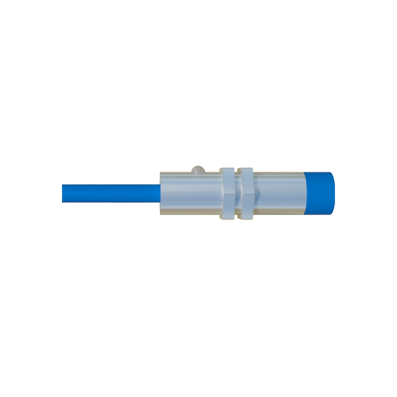
For a 1cm application, both inductive and capacitive proximity switches are common choices. Inductive sensors are ideal for detecting metallic objects at this short range with high precision and switching frequency. If the target is non-metallic, a capacitive sensor is required. When selecting, verify the "assured operating distance" (Sa), which is typically 0.9 times the nominal distance, accounting for manufacturing tolerances and industrial variables. For a reliable 1cm detection, a sensor with a nominal distance slightly greater than 1cm (e.g., 1.5cm or 2cm) is often recommended. This provides a built-in safety factor, ensuring consistent triggering even with target misalignment or buildup of contaminants.
Wiring Configuration and Electrical Connections
Proximity sensors are typically available in three-wire (DC) or two-wire (AC/DC) configurations. For precise 1cm applications, three-wire DC sensors (PNP or NPN) are preferred due to their stable switching characteristics. The standard wiring involves connecting the brown wire (or L+) to the positive DC supply voltage (e.g., 24V DC), the blue wire (or L-) to the negative/common DC supply, and the black wire as the switched output signal. The load (e.g., a PLC input, relay coil, or indicator) is connected between the black wire and the opposite supply rail (for PNP: between black and blue/negative; for NPN: between black and brown/positive). Always ensure the power supply matches the sensor's voltage rating and is properly filtered.
Installation and Mounting Considerations
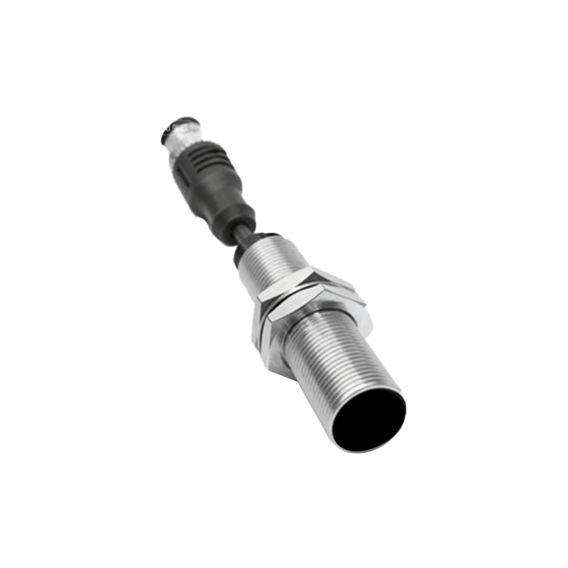
Precise mechanical mounting is paramount for consistent 1cm operation. The sensor must be securely fixed to prevent vibration-induced distance changes. Flush-mountable sensors can be installed level with a metal bracket, while non-flush types require a clear lateral space free of surrounding metal to maintain their sensing field. The approach direction of the target should be perpendicular to the sensor's sensing face. Parallel alignment is critical; even a slight angular misalignment can effectively reduce the operational sensing distance, causing intermittent failures. Use mounting brackets or adjustable fixtures to fine-tune and lock the position.
Adjustment and Calibration for Precise Detection
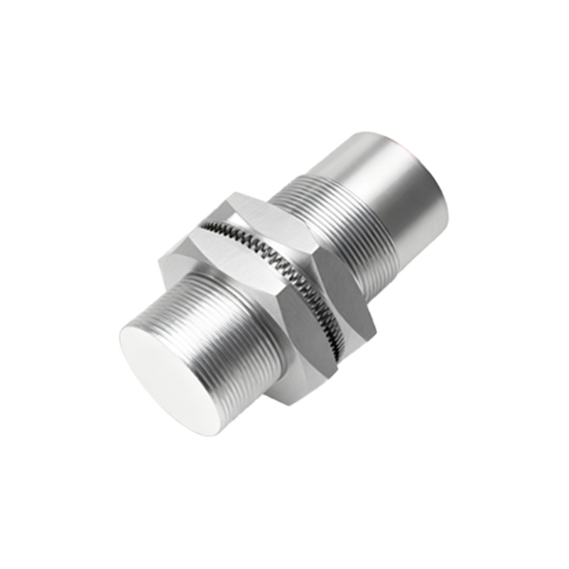
While most modern proximity sensors are non-adjustable, ensuring the exact 1cm gap requires careful setup. Use precision gauges or shims to set the distance between the sensor's face and the target in its "home" position. For applications requiring hysteresis adjustment (the difference between switch-on and switch-off points), some sensors feature a potentiometer. Turn this potentiometer carefully while monitoring the output with the target at the 1cm position to achieve the desired switching behavior. Always perform testing with the actual target material under real operational conditions (powered machinery, typical temperatures) to validate the setup.
Troubleshooting Common Connection Issues
If the sensor fails to detect reliably at 1cm, follow a systematic check. First, verify power supply voltage and polarity with a multimeter. Second, check for electrical noise by temporarily routing sensor cables away from power lines or motors. Third, inspect the target: ensure it is the correct material, size, and is approaching correctly. A target smaller than the sensor's face or made of the wrong metal (e.g., aluminum for an inductive sensor) reduces the effective sensing distance. Fourth, use an LED indicator on the sensor or a multimeter to confirm the output signal is switching. Persistent issues may indicate a need for a sensor with a higher nominal range or different technology.