Understanding Photoelectric Sensor Fundamentals
Photoelectric sensors are indispensable components in modern industrial automation, relying on light beams to detect the presence, absence, or distance of objects. Their operation hinges on three primary components: an emitter (light source), a receiver, and a signal processor. The emitter projects a light beam—often infrared, visible red, or laser—toward the receiver. When an object interrupts or reflects this beam, the receiver detects the change in light intensity, prompting the signal processor to trigger an output signal. This fundamental principle underpins their application across diverse sectors, from packaging and material handling to automotive assembly and pharmaceutical production. The reliability of these sensors, however, is not solely dependent on their intrinsic quality but is profoundly influenced by their physical placement and integration within a system.
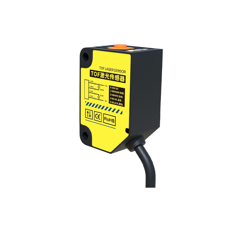
Key Factors Influencing Sensor Positioning
Strategic placement is critical for maximizing sensor efficacy and ensuring long-term operational stability. Several environmental and application-specific factors must be meticulously evaluated. First, the sensing range and beam characteristics must match the target object's size, material, and surface properties. A glossy or reflective surface may cause beam deflection, leading to false triggers, while dark or absorbent materials might require a sensor with higher sensitivity or a specific wavelength. Second, ambient light conditions pose a significant challenge. Direct sunlight or intense artificial lighting can saturate the receiver, causing malfunction. Employing modulated light signals (where the emitter pulses at a specific frequency) and sensors with robust ambient light immunity is essential in such environments. Third, mechanical factors like vibration, shock, and potential physical damage from passing objects necessitate secure mounting and, often, protective housings. Finally, the alignment between emitter and receiver must be precise and stable; even minor shifts due to thermal expansion or vibration can degrade performance.
Best Practices for Through-Beam Sensor Alignment
Through-beam (or opposed) sensors, with separate emitter and receiver units, offer the longest sensing distances and highest reliability for clear object detection. Optimal placement requires a direct, unobstructed line of sight. During installation, use alignment tools or the sensor's built-in indicators to ensure the beam is perfectly centered on the receiver's aperture. Mount both units on rigid, stable structures to prevent misalignment over time. For applications detecting small objects, ensure the beam is narrower than the target's smallest dimension. Consider the "beam divergence"—the gradual widening of the beam over distance—which can affect detection consistency for very small parts at long ranges. Regular maintenance checks should verify alignment, as process vibrations or accidental impacts are common causes of drift.
Optimizing Reflective and Diffuse Sensor Placement
Reflective (retro-reflective) and diffuse (proximity) sensors integrate the emitter and receiver into a single housing, simplifying installation. For retro-reflective types, which use a reflector, placement must ensure the beam returns accurately. Avoid positioning where shiny objects or background surfaces could create competing reflections. The sensor should be angled slightly off-perpendicular to the reflector to prevent direct optical feedback. For diffuse sensors, which detect light reflected directly from the target, distance and angle are paramount. The effective sensing distance can vary dramatically based on the target's color and texture. Perform rigorous testing with actual production samples to establish the optimal stand-off distance. A common best practice is to mount the sensor slightly closer than its maximum rated distance for the specific target to create a safety margin against process variations.
Mitigating Environmental Interference
Industrial environments are rife with potential interference. Dust, fog, steam, and oil mist can scatter or attenuate the light beam, reducing effective range or causing false negatives. In such conditions, consider sensors with higher output power or specific lens designs that minimize surface contamination buildup. Air blow-off devices or protective windows (with appropriate anti-reflective coatings) can keep the lens clean. Electrical noise from motors, welders, or variable frequency drives can disrupt sensor electronics. Ensure proper grounding, use shielded cables, and separate sensor wiring from high-power lines. Thermal effects, both from ambient temperature swings and self-heating, can alter optical component properties and electronic drift; select sensors with wide operating temperature ranges and stable thermal characteristics for critical applications.
Integration with Control Systems and Diagnostics
The sensor's physical location must also facilitate effective integration with the broader control system, such as a PLC. Position sensors to allow for accessible wiring and connection points. Consider diagnostic capabilities: many modern sensors offer IO-Link or similar digital interfaces that provide real-time data on signal strength, operating temperature, and contamination levels. Placing sensors in locations where this data can be easily monitored aids in predictive maintenance. Furthermore, the placement should support logical troubleshooting access. A sensor buried deep within a machine may function initially but becomes a maintenance nightmare. Designing for serviceability by leaving adequate space around the sensor for tools and calibration devices reduces downtime.
Conclusion: A Systematic Approach to Placement
Achieving optimal photoelectric sensor performance is an engineering discipline that extends beyond simple component selection. It demands a systematic approach to placement, considering optical, mechanical, environmental, and operational factors in unison. There is no universal formula; each application presents a unique set of constraints. Successful implementation involves prototyping with real-world conditions, continuous monitoring, and a willingness to adjust. By treating sensor positioning as a critical design parameter, engineers can significantly enhance system reliability, reduce false stops, and improve overall production efficiency. The goal is to make the sensing function so robust and transparent that it becomes an invisible, yet utterly dependable, facilitator of automation.