Introduction to Through-Beam Photoelectric Sensors
Through-beam photoelectric sensors, also known as opposed-mode sensors, are a fundamental component in industrial automation. They consist of two separate units: a transmitter and a receiver. The transmitter emits a continuous beam of light, typically infrared or visible red, which is then detected by the receiver. An object is sensed when it physically interrupts this light beam. This configuration offers the longest sensing range and highest reliability among photoelectric sensing modes, as it is less susceptible to environmental factors like surface color, texture, or reflectivity. These sensors are widely used for object detection, counting, and safety applications in manufacturing, packaging, and material handling systems. Their robust performance in challenging conditions makes them a preferred choice for precise detection tasks.
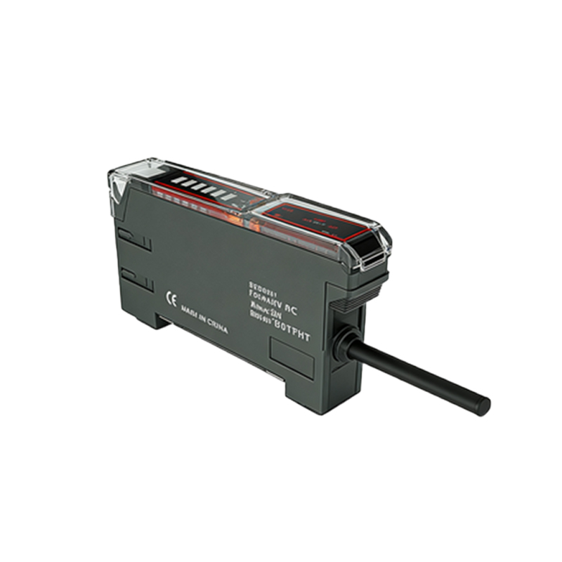
Core Components and Operating Principle
The transmitter unit houses a light-emitting diode (LED) that generates the modulated light beam. Modulation, or pulsing the light at a specific frequency, allows the receiver to distinguish the sensor's signal from ambient light, significantly enhancing noise immunity. The receiver contains a phototransistor or photodiode tuned to the transmitter's frequency. When the light beam is uninterrupted, the receiver's output is in one state (often termed "light-on" or "dark-on," configurable by the user). The moment an object breaks the beam, the receiver's output switches to the opposite state, sending a signal to the connected controller like a PLC. This simple yet effective "break-beam" principle provides highly accurate and fast response times.
Standard Through-Beam Wiring Configurations
Correct wiring is critical for sensor operation and system safety. Most industrial through-beam sensors operate on DC voltages (commonly 12-24V DC) or sometimes AC. The wiring diagram fundamentally involves connecting power to both units and wiring the receiver's output signal. For a standard 3-wire DC sensor, the receiver typically has three leads: Brown wire for positive DC supply (+V), Blue wire for common negative (0V), and a Black (or sometimes White) wire as the switched output signal. The transmitter usually has two wires: Brown (+V) and Blue (0V). The output from the receiver's black wire is connected to the input of a PLC or relay. It is crucial to consult the specific sensor's datasheet, as wire colors and functions can vary by manufacturer.
Detailed Wiring Diagram and Step-by-Step Connection
A typical wiring setup for a 24V DC system is as follows. First, connect the 24V DC positive terminal from the power supply to the brown wires of both the transmitter and the receiver. Second, connect the 0V DC negative terminal to the blue wires of both units. This provides operating power. Third, connect the receiver's output (black wire) to one terminal of the PLC's digital input module. Finally, connect the other terminal of that PLC input to the 0V DC line (often referred to as a "sinking" input configuration). Some sensors offer a choice between NPN (sinking) and PNP (sourcing) output transistors. NPN outputs switch the negative (0V) line, while PNP outputs switch the positive (+V) line; the choice must match the PLC input type. Always ensure the electrical load (the PLC input) does not exceed the sensor's rated output current.
NPN vs. PNP Output Types in Wiring
Understanding NPN and PNP outputs is essential for correct integration. An NPN output sensor, common in Asia and many global designs, has a black output wire that acts as a switch to the negative (0V) line. When active, it connects the load to 0V. This is used with a PLC input card wired to receive a "sinking" signal. Conversely, a PNP output sensor, prevalent in Europe and North America, uses the black output wire to switch the positive voltage (+V) to the load. It is used with a "sourcing" type PLC input. Mis matching these can lead to non-operation or potential damage. The wiring diagram for each type differs in where the PLC input's common wire is connected—to +V for NPN sensors and to 0V for PNP sensors.
Safety Considerations and Best Practices
Implementing through-beam sensors requires adherence to safety protocols. Always disconnect power before wiring. Use shielded cables in electrically noisy environments and ground the shield at one end to prevent interference. Ensure the sensor's voltage rating matches the supply. For long cable runs, consider voltage drop and use appropriately gauged wires. Physically align the transmitter and receiver precisely; misalignment is a common cause of failure. Many models have alignment indicators like LEDs. For safety light curtains, which are multi-beam through-beam systems, follow all manufacturer instructions and applicable standards (e.g., IEC 61496) to ensure personnel protection. Regular maintenance, including lens cleaning to prevent dust accumulation, is vital for sustained reliability.
Troubleshooting Common Wiring Issues
Several issues can arise from incorrect wiring. If the sensor does not power on, verify voltage at the sensor terminals and check for reversed polarity. If the output seems erratic or the sensor is always triggered, it may indicate misalignment, dirty lenses, or severe ambient light interference. An output that never changes state despite a broken beam could point to a wiring error between the output and the PLC input, or a mismatch between NPN/PNP output and PLC input type. Using a multimeter to check voltage at the output wire relative to the blue (0V) wire during beam interruption is a key diagnostic step. The datasheet's status LED explanations are invaluable for troubleshooting.
Application Examples in Automation
Through-beam sensors are deployed in diverse scenarios. In conveyor systems, they detect the presence of boxes for counting or triggering downstream processes. In packaging machinery, they ensure a product is in place before sealing or filling. As safety devices, they create invisible barriers around hazardous areas on machines; breaking the beam initiates an immediate stop. In the automotive industry, they verify component placement on assembly lines. Their long range allows detection of large objects or use across wide conveyors. The reliability of the through-beam mode makes it indispensable for these critical tasks where false readings are unacceptable.
Conclusion and Final Recommendations
A properly wired through-beam photoelectric sensor is a reliable workhorse for industrial detection. Success hinges on selecting the correct voltage, understanding the output type (NPN/PNP), and following the precise wiring diagram for your specific model. Always prioritize manufacturer documentation over generic guides. Correct alignment and environmental protection are as important as the electrical connections. By mastering these wiring fundamentals, engineers and technicians can ensure robust sensor performance, minimizing downtime and maximizing efficiency in automated systems. This knowledge forms a cornerstone of effective industrial electrical and control system design.