Understanding Proximity Sensor Fundamentals
Proximity sensors are non-contact electronic devices designed to detect the presence or absence of an object within a specified sensing range. They operate on various principles, primarily inductive, capacitive, ultrasonic, and photoelectric. Inductive sensors detect metallic objects by generating an electromagnetic field. Capacitive sensors can detect both metallic and non-metallic materials by sensing changes in capacitance. Ultrasonic sensors use sound waves, while photoelectric sensors rely on light beams. The core function is to provide a discrete output signal, typically a switch signal, when a target enters the detection zone. This output is crucial for automation processes like counting, positioning, inspection, and safety interlocking. Selecting the wrong type can lead to system failures, false triggers, or reduced efficiency, making a fundamental understanding the critical first step in any selection process.
Defining Key Application Parameters
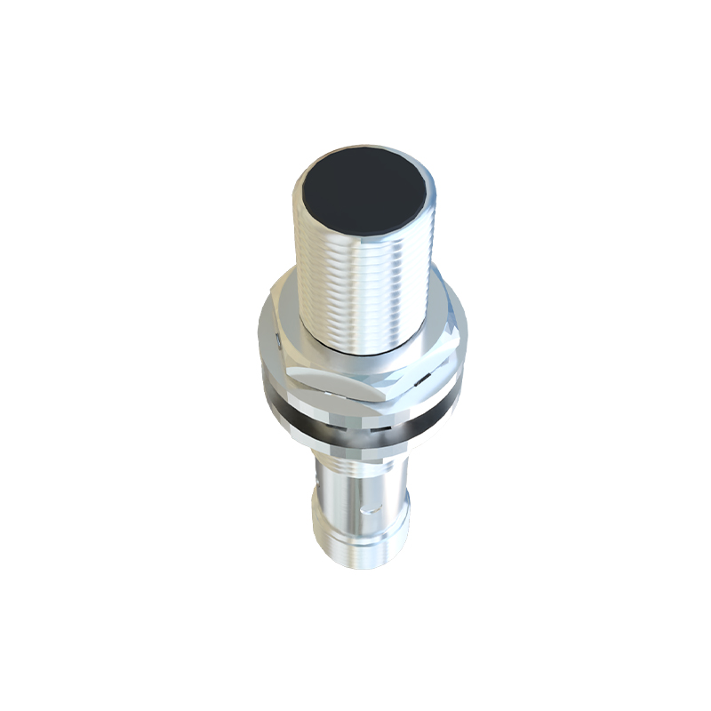
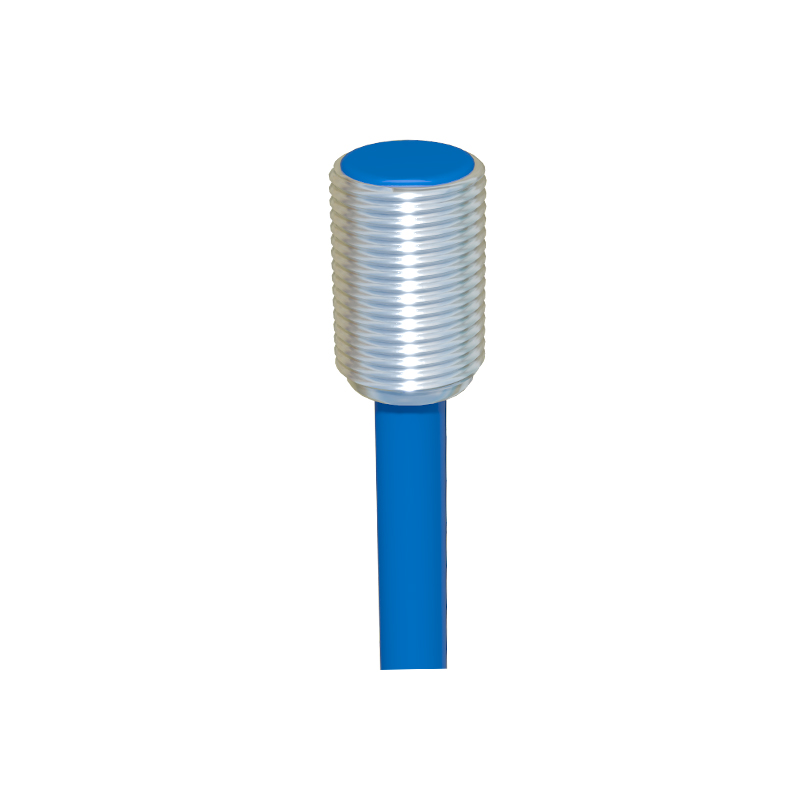
Before any calculation, clearly define the application's specific requirements. The primary parameters include the target material, size, and shape. For inductive sensors, the target material's type (e.g., steel, aluminum, copper) and size directly affect the sensing distance. The required sensing distance, or nominal range (Sn), is the distance from the sensor face at which a standard target triggers the switch. The installation environment is equally vital; consider factors like ambient temperature, presence of dust, oil, coolant, or strong electromagnetic interference. The required switching frequency (how many detections per second) and the output type (PNP/NPN, NO/NC, analog, IO-Link) must match the controller's input specifications. Finally, the physical constraints, such as available space and required housing style (barrel, rectangular, ring), dictate the sensor's form factor.
Calculating the Correct Sensing Distance
The nominal sensing distance (Sn) listed in datasheets is measured under ideal conditions with a standard target. Real-world applications rarely match these conditions. Therefore, derating or applying correction factors is essential. For inductive sensors, the effective sensing distance (Sr) is calculated based on the target material and size. A reduction factor is applied for non-ferrous metals like aluminum or copper. For example, if an inductive sensor has an Sn of 10mm for mild steel, it might only sense aluminum at 40% of that distance, or 4mm. The target size must also be considered; if the target is smaller than the sensor's active face diameter, a further reduction is necessary. A safe practice is to select a sensor with a nominal range (Sn) that is 2 to 3 times the required actual installation distance to account for mechanical tolerances, temperature drift, and voltage fluctuations.
Accounting for Temperature and Voltage Effects
Sensor performance is not static. Operating temperature and supply voltage variations can significantly alter the sensing characteristics. Most proximity sensors have a specified operating temperature range (e.g., -25°C to +70°C). Within this range, the sensing distance may drift, typically within ±10% of the nominal value at 20°C. High temperatures can reduce the sensing distance and potentially damage the sensor. Similarly, supply voltage variations can affect the output switching point. A sensor rated for 10-30V DC might exhibit a change in switching distance if the voltage drops to the lower limit. When calculating for critical applications, consult the manufacturer's datasheet for temperature and voltage drift graphs. Always design with a safety margin, ensuring the sensor will function reliably at the extremes of the specified voltage and temperature conditions in your application.
Selecting Housing and Output Configuration
The mechanical and electrical integration of the sensor is paramount. The housing material (typically stainless steel, brass, or PBT plastic) must withstand the environmental challenges, such as chemical exposure, washdowns, or physical impact. The ingress protection (IP) rating (e.g., IP67, IP69K) indicates resistance to dust and water. For output configuration, the choice between PNP (sourcing) and NPN (sinking) is determined by the PLC or controller's input module type. Similarly, selecting normally open (NO) or normally closed (NC) contacts depends on the safety and logic requirements of the circuit. For advanced applications, sensors with analog outputs (4-20mA, 0-10V) or digital communication protocols like IO-Link provide continuous data on distance or allow for parameterization, enabling predictive maintenance and finer process control.
Verifying Selection with Practical Checks
After theoretical selection and calculation, practical verification is crucial. Create a test setup that mimics the real application as closely as possible. Measure the actual sensing distance with the specific target material under normal operating voltage and temperature. Check for false triggering caused by nearby metal objects