Introduction to Hourglass Proximity Sensors
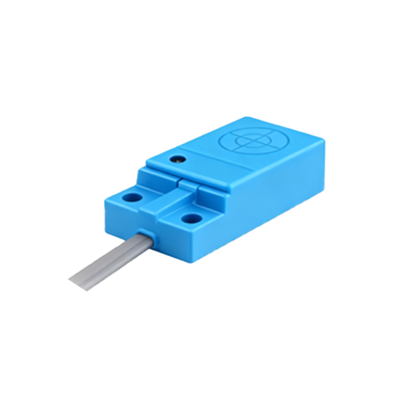
Hourglass proximity sensors, named for their distinctive tapered, symmetrical shape, represent a specialized category of non-contact detection devices widely employed in industrial automation. Their unique form factor is engineered to provide superior performance in confined spaces and challenging environments where standard cylindrical sensors may not fit or function optimally. These sensors operate on fundamental principles such as inductive, capacitive, or photoelectric sensing, generating an electrical signal when a target object enters their predefined detection field. Their reliability is paramount for critical processes including precise positioning, object counting, and automated safety interlocks across manufacturing, packaging, and material handling systems.
Common Symptoms of Sensor Anomalies
Identifying a malfunctioning hourglass proximity sensor requires vigilance for specific irregular behaviors. The most frequent symptom is intermittent operation, where the sensor's output signal fluctuates erratically without corresponding changes in the target's position. This may manifest as the controlled machine cycling unpredictably. Another clear indicator is a complete failure to detect, where the sensor does not activate even when a target is well within its specified sensing range. Conversely, a sensor may exhibit constant activation, remaining in a triggered state regardless of target presence, which can halt production lines. Unstable sensing distance, where the effective range shrinks or varies, and excessive temperature rise of the sensor housing are also critical signs of underlying issues.
Primary Causes of Abnormal Operation
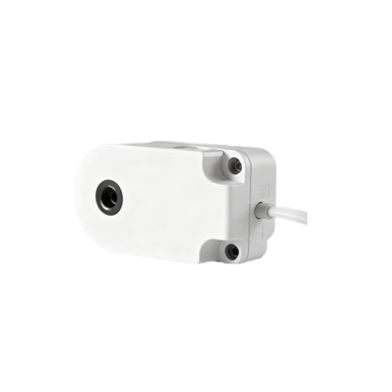
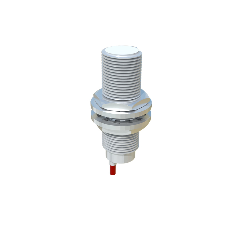
Multiple factors can lead to the abnormal performance of hourglass proximity sensors. Environmental contamination stands as a leading cause; accumulation of metallic dust, chips, oil, or coolant on the active sensing face can severely attenuate or distort the detection field. Electrical interference is another major culprit, often originating from nearby high-voltage cables, frequency drives, welding equipment, or other sensors, inducing noise into the signal lines. Mechanical damage, such as cracks in the housing or internal dislodgement from vibration, compromises integrity. Power supply problems, including voltage spikes, sags, or incorrect wiring, directly impact sensor electronics. Finally, internal component degradation over time, such as capacitor failure or oscillator drift, leads to performance decay.
Systematic Troubleshooting Methodology
A structured approach is essential for efficient diagnosis. Begin with a visual and physical inspection of the sensor, its mounting, and the surrounding area for obvious damage, debris, or misalignment. Verify the electrical connections, ensuring proper voltage (e.g., 10-30V DC) at the sensor terminals according to the datasheet, and check for secure, corrosion-free terminals and conduit entries. Next, perform a functional test using a known-good target. Measure the actual sensing distance and compare it to the sensor's specifications. Utilize an oscilloscope to monitor the output signal for noise or instability. Temporarily replace the suspect sensor with a verified unit is a highly effective isolation step. Always consult the manufacturer's diagnostic guidelines specific to the sensor model.
Preventive Maintenance and Best Practices
Proactive maintenance significantly reduces anomaly rates. Establish a regular cleaning schedule using appropriate solvents and non-abrasive tools to keep the sensing face free of contaminants. Ensure proper shielding and grounding of both the sensor and its cabling; use shielded cables and route them away from power lines. Implement correct mounting procedures, avoiding over-torquing and ensuring the sensor is not subjected to direct physical impact from targets. Where vibration is present, use vibration-dampening mounts. Maintain stable, clean power by using regulated power supplies or noise filters. Keep detailed logs of sensor performance, replacements, and environmental conditions to identify patterns and predict failures.
When to Repair or Replace
The decision to repair or replace a faulty hourglass sensor depends on several factors. Replacement is typically the most cost-effective and reliable solution for sensors showing internal electronic failure, physical damage to the body or sensing element, or significant performance deviation outside recalibration limits. Modern industrial sensors are often sealed units not designed for field repair. Consider repair only if the issue is purely external, such as a damaged connector that can be professionally re-terminated. Always weigh the cost of downtime against the sensor's price. For critical applications, immediate replacement with a spare is advised. Upgrading to a newer model with enhanced environmental ratings or diagnostics may be a strategic long-term decision.
Conclusion and Key Takeaways
Hourglass proximity sensor anomalies, while disruptive, are manageable through systematic understanding and practice. Recognizing early symptoms like intermittent operation or unstable range allows for prompt intervention. Root causes typically revolve around environmental, electrical, and mechanical stressors. Adherence to a logical troubleshooting workflow—inspection, verification, testing, and isolation—enables rapid fault identification. Ultimately, a robust preventive maintenance program centered on cleanliness, proper installation, and electrical integrity is the