Introduction to U-Groove L-Type Photoelectric Sensors
U-groove L-type photoelectric sensors represent a specialized category of through-beam sensors, distinguished by their unique mechanical design. These sensors feature a U-shaped groove that allows the sensing object to pass through the gap between the emitter and receiver, which are mounted on opposite arms of the "U." The "L-type" designation typically refers to the physical housing shape, which often facilitates easier mounting and alignment in space-constrained industrial environments. This configuration is fundamentally different from diffuse or retro-reflective models, as it relies on a direct, unobstructed light beam. The interruption of this beam by an object triggers the sensor's output. This design principle makes them exceptionally reliable for detecting small, fast-moving, or transparent objects that might challenge other sensing technologies. Their robustness against environmental interference, such as ambient light or target surface characteristics, is a key advantage derived from this through-beam methodology.
Core Operating Principles and Technical Specifications
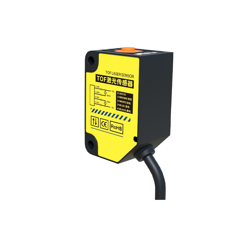
At the heart of a U-groove L-type sensor lies a precise optical system. An infrared or visible light-emitting diode (LED) in one arm projects a focused beam directly onto a phototransistor or photodiode receiver in the opposite arm. The sensor's electronics continuously monitor the intensity of the received light. When an object enters the U-groove and breaks the beam, the received light level drops, causing the sensor's output circuit to change state—typically from a high to low signal or vice versa, depending on whether it is configured as light-on or dark-on. Key technical specifications include sensing distance (the width of the U-groove gap), response time (often in microseconds), light source type, and output configuration (NPN/PNP transistor, analog, or digital). The narrow, precise beam and the physical separation of emitter and receiver contribute to high repeat accuracy and a distinct sensing window, minimizing false triggers.
Advantages in Harsh Industrial Environments
The enclosed nature of the U-groove design offers inherent benefits in challenging settings. It provides a degree of mechanical protection for the optical components against dust, chips, and minor physical impacts. Many industrial-grade models are built with rugged housings from materials like nickel-plated brass or stainless steel, offering resistance to corrosion, oils, and coolants. Furthermore, the through-beam principle itself is largely immune to problems caused by the color, reflectivity, or surface finish of the target object. Whether detecting a glossy metal part, a transparent glass vial, or a matte plastic component, the sensor performs consistently as long as the object is opaque enough to interrupt the beam. This reliability is crucial in automated assembly, packaging, and material handling lines where process continuity is paramount.
Typical Application Scenarios and Installation Best Practices
These sensors find widespread use across manufacturing and automation. Common applications include object counting on conveyors, detecting the presence or absence of components in assembly jigs, verifying the passage of items through a chute, monitoring breakage of wires or filaments, and ensuring proper positioning in machinery. For optimal performance, correct installation is critical. The sensor must be securely mounted so that the target object reliably passes through the center of the U-groove without touching the inner walls. Alignment is generally fixed by the housing, eliminating the need for precise optical alignment required by separate emitter-receiver pairs. However, installers must ensure that no persistent obstructions or build-up of debris within the groove occurs, as this would permanently break the beam. Regular cleaning of the lens windows is recommended in dirty environments.
Selection Criteria and Integration Considerations
Choosing the right U-groove L-type sensor requires evaluating several application parameters. The primary factor is the groove width, which must accommodate the size and possible sway of the target object. The required response speed must match the object's velocity. Output type must be compatible with the programmable logic controller (PLC) or other control system input card (sinking vs. sourcing). Environmental conditions dictate the necessary ingress protection (IP) rating. For detecting very small objects, a sensor with a narrow, focused beam is essential. Some advanced models offer features like adjustable sensitivity, built-in amplifiers, or diagnostic LEDs. When integrating, electrical considerations such as supply voltage (commonly 10-30V DC), current draw, and wiring (2-wire, 3-wire, or 4-wire) must be adhered to according to the datasheet to ensure safe and reliable operation.
Future Trends and Maintenance Guidelines
The evolution of U-groove L-type sensors aligns with broader Industry 4.0 trends. Future iterations may incorporate IO-Link communication for digital parameter setting, remote monitoring, and predictive maintenance data. Enhanced resistance to extreme temperatures and more robust housing materials are ongoing development areas. For maintenance, a proactive approach ensures longevity. Besides routine lens cleaning, periodic checks for mechanical integrity (loose mounts, damaged housing) and verification of output signal stability are advised. Understanding that the primary failure modes often involve lens contamination or physical damage to the housing helps in troubleshooting. With proper selection, installation, and care, U-groove L-type photoelectric sensors provide a long-lasting, highly reliable solution for precise object detection in demanding automation tasks.