Introduction to Retro-Reflective Photoelectric Sensors
Retro-reflective photoelectric sensors, commonly utilizing a laser light source, are fundamental components in industrial automation. They operate on a simple yet effective principle: the sensor's emitter sends a light beam towards a specialized reflector, which returns the beam directly to the sensor's receiver. An object interrupting this beam path triggers the sensor's output. This setup offers significant advantages over through-beam sensors by requiring wiring only on one side of the detection area, simplifying installation and reducing cost. Their reliability, long sensing ranges, and precise detection capabilities make them ideal for applications like object counting, positioning, and presence detection in packaging, material handling, and assembly lines.
Pre-Installation Planning and Safety
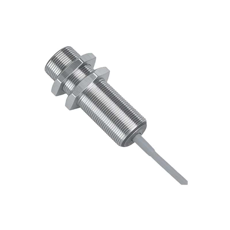
Before physical installation, thorough planning is essential. First, review the sensor's datasheet to confirm its specifications, including sensing distance, light source type (e.g., visible red laser), supply voltage, output type (PNP/NPN, NO/NC), and environmental ratings (IP67, etc.). Select an appropriate reflector. Standard retro-reflective targets consist of numerous tiny corner cubes that return light to its source with minimal scatter. Ensure the reflector size and pattern are suitable for the required sensing distance and beam spot size. Always adhere to laser safety standards (e.g., IEC 60825-1). Never look directly into the laser beam or its reflection. For visible lasers, use caution indicators. Power down the entire system during mechanical mounting and wiring to prevent electrical hazards or accidental activation.
Mechanical Mounting and Alignment
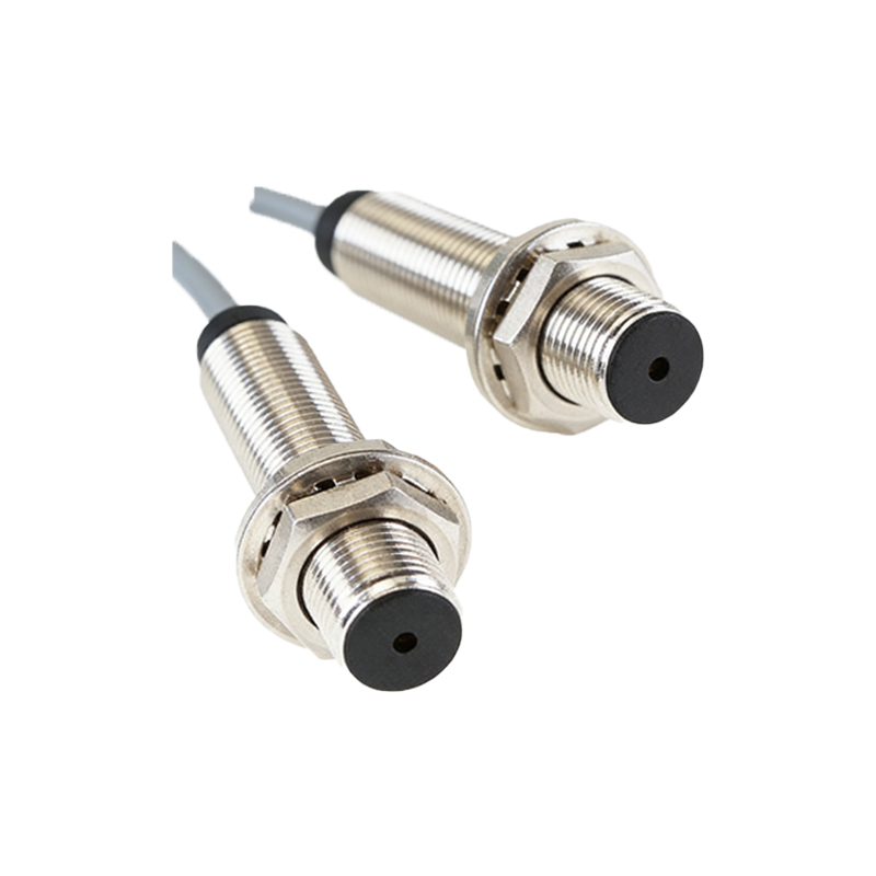
Secure the sensor and reflector on stable, vibration-free mounts. Precise alignment is critical for optimal performance. Initially, roughly align the sensor and reflector visually. For sensors with a visible laser, this process is straightforward. Power the sensor and use the alignment indicators, if available. Many sensors feature a built-in alignment aid, such as a stability LED that changes color or intensity when the received light is sufficient. Fine-tune the sensor's horizontal and vertical angles until the alignment indicator shows peak signal strength. Ensure the beam path is clear of obstructions and potential sources of optical interference, such as reflective surfaces (polished metal, glass) or highly glossy objects that could create false reflections. Maintaining a clean lens and reflector surface is paramount; dust or grease can drastically reduce sensing reliability.
Electrical Wiring and Connection
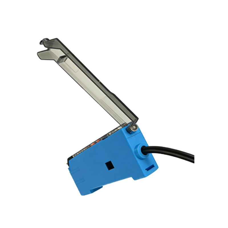
Follow the wiring diagram provided in the sensor's manual meticulously. Typically, connections include power supply (Vcc and GND), output signal, and, optionally, a teach-in wire or diagnostic output. Use shielded cables in electrically noisy environments, grounding the shield at the controller end only to prevent ground loops. For DC sensors, observe correct polarity. If the sensor features programmable functions (e.g., setting light-on/dark-on mode, output delay timers), configure these via push buttons or an external teach wire according to the application needs. After wiring, perform a preliminary check: apply power and verify the sensor's power LED illuminates. Pass an object through the beam to confirm the output signal switches states. Use a multimeter or PLC input to monitor the signal integrity.
Adjusting Sensitivity and Setting the Detection Window
Modern retro-reflective sensors often include a sensitivity potentiometer or digital settings. The goal is to set a threshold that reliably detects the target object while ignoring ambient light, minor dust accumulation, or slight misalignment drift. Start with the sensitivity at maximum. With the reflector properly aligned and no target present, the sensor should be in its "normal" state (e.g., output OFF for light-on mode). Gradually decrease the sensitivity until the alignment indicator shows the signal is just above the switching threshold, providing a good safety margin. For challenging environments with dust or steam, a background suppression feature or a modulated light source (pulsed laser) is highly recommended to ignore false reflections. Some advanced sensors allow setting a "window" for detection, where only an object within a specific distance range triggers the output, adding another layer of discrimination.
Testing and Troubleshooting Common Issues
Conduct comprehensive testing under actual operating conditions. Test with the intended target objects moving at the expected speeds. Check for consistent triggering. Common issues include unreliable detection, which may stem from poor alignment, dirty optics, insufficient sensitivity, or electrical noise. Use the sensor's signal strength indicator (often a series of LEDs) to diagnose alignment and signal quality. If the sensor triggers without an object, investigate potential reflective interferences or external light sources (sunlight, welding arcs). Installing a polarizing filter (for sensors with polarized lenses) can help reject reflections from shiny objects. For noise issues, ensure proper cable routing away from power lines and motors, and verify grounding. Always consult the manufacturer's troubleshooting guide for specific error codes or behaviors.
Maintenance and Best Practices for Long-Term Operation
Establish a routine maintenance schedule. Regularly inspect and clean the sensor lens and reflector with a soft, lint-free cloth and appropriate cleaner. Check mounting hardware for tightness, as vibration can cause misalignment. Periodically verify the sensing function and signal strength. Document the initial sensitivity setting and alignment condition for future reference. Implement protective measures such as physical guards to prevent mechanical damage to the sensor or beam path. In harsh environments, consider sensors with robust housings and higher ingress protection ratings. Keeping a log of performance data can help predict failures and plan preventive maintenance, ensuring continuous and reliable operation of the automation system.