Introduction to Through-Beam Photoelectric Sensors
A through-beam photoelectric sensor, often referred to as a "beam-break" sensor, is a fundamental component in industrial automation and safety systems. It operates on a straightforward principle: a separate emitter unit projects a beam of light—typically infrared, visible red, or laser—towards a dedicated receiver unit positioned directly opposite. The core function is to detect the presence or absence of an object that interrupts this continuous light beam. This configuration offers the longest sensing range and highest reliability among photoelectric sensor types, as it is less susceptible to surface color, texture, or reflectivity of the target object. The schematic diagram of such a system is key to understanding its electrical integration, signal processing, and interface with control systems like PLCs (Programmable Logic Controllers).
Key Components in the Schematic
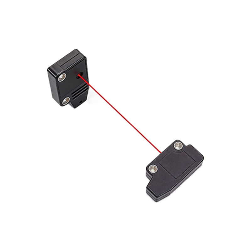
Examining a standard schematic reveals two primary blocks: the Emitter Circuit and the Receiver Circuit. The emitter circuit is relatively simple. Its heart is a light-emitting element, usually an LED (Light Emitting Diode) for infrared or visible light, or a laser diode for precise, long-range applications. The schematic shows this diode connected in series with a current-limiting resistor to a DC power supply (e.g., 12-24V DC). A constant current source circuit is often incorporated to ensure stable light output intensity, which is critical for consistent performance over time and temperature variations. The receiver circuit is more complex. Its central component is a phototransistor or a photodiode, which acts as the light-sensitive element. When the beam from the emitter strikes it, it conducts current. This circuit includes amplification stages using operational amplifiers (op-amps) to boost the weak photocurrent signal. Following amplification, a comparator circuit is employed. This comparator compares the amplified signal against a preset reference voltage (threshold). If the received light intensity is above the threshold, the output is in one state (e.g., logic HIGH or relay closed); if the beam is interrupted and intensity falls below the threshold, the output switches state.
Output Configuration and Wiring
The output stage of the receiver is a critical part of the schematic, defining how the sensor communicates with external machinery. Common output types include NPN (sinking), PNP (sourcing), and relay contacts. In an NPN output schematic, the load (e.g., a PLC input) is connected between the sensor's output wire and the positive supply voltage (+V). The NPN transistor inside the sensor acts as a switch to ground (0V). When the beam is unbroken and the sensor is active, the transistor turns on, connecting the output to ground, thus "sinking" current through the load. A PNP output schematic is the opposite; the load is connected between the output and ground, and the internal PNP transistor switches the positive voltage to the load. Relay outputs are shown with standard coil and contact symbols, providing isolated switching for AC or DC loads. The schematic clearly labels power supply terminals (V+, V-, or COM), output signal lines, and often a wire for an output status LED indicator.
Timing and Control Logic
Advanced through-beam sensors incorporate timing functions, which are represented in the schematic by logic symbols or dedicated timer ICs. These functions include On-Delay, Off-Delay, and One-Shot pulse outputs. The schematic shows how the comparator's output signal is fed into this logic circuit. For instance, in an On-Delay mode, the logic circuit prevents the final output from switching ON until the beam has been continuously interrupted for a user-set time period, effectively debouncing the signal to ignore fleeting interruptions. This logic is crucial for rejecting false triggers from fast-moving debris or environmental factors like dust. The control logic block ensures the output provides a clean, definitive signal to the master control system.
Practical Considerations from the Schematic
A thorough analysis of the schematic provides practical installation and troubleshooting insights. The diagram emphasizes the necessity of a stable, clean power supply, often showing recommended decoupling capacitors near the ICs to filter electrical noise. It highlights the importance of correct polarity for both the emitter and receiver. Miswiring the DC supply can instantly damage the internal electronics. For long-range applications, the schematic may indicate connections for alignment aids, such as a built-in alignment LED that brightens as the beam is correctly centered on the receiver. Understanding the signal flow from the photodetector to the final output allows technicians to systematically diagnose faults. For example, using an oscilloscope, one can probe the signal after the amplifier to see if the light interruption is being detected, even if the final output is not responding, thereby isolating the fault to the logic or output stage.
Integration with Control Systems
The final part of a through-beam sensor's schematic often details its interface with broader industrial controls. The output wire is typically shown connecting to the input module of a PLC. The schematic specifies whether the PLC input should be configured as sinking or sourcing to match the sensor's output type. It may also show protective components like a flyback diode across an inductive load (e.g., a relay coil) or a fuse for overcurrent protection. In safety-critical applications, such as light curtains, the schematic will depict redundant circuits and self-checking (monitoring) loops that continuously test the emitter's output and the receiver's functionality, with separate safety-rated output signals (OSSDs - Output Signal Switching Devices) that comply with standards like IEC 61496. This integration view is essential for designing a reliable and safe automated system.