Understanding Proximity Sensor Basics
Proximity sensors are essential components in industrial automation, detecting the presence or absence of an object without physical contact. They come in various types, primarily inductive (for metals), capacitive (for various materials including liquids), and photoelectric. Before wiring, it is crucial to identify your sensor type and its specific electrical characteristics. Check the datasheet for key parameters: operating voltage (commonly 10-30V DC or 90-250V AC), output type (PNP/NPN for DC, or relay/NO/NC for AC), and current rating. The housing is typically marked with wiring diagrams and terminal designations. Safety is paramount; always disconnect power before starting any wiring work. Ensure you have the correct tools, such as wire strippers, screwdrivers, and appropriate gauge wires as specified by the sensor manufacturer.
Deciphering the Wiring Diagram and Terminal Labels
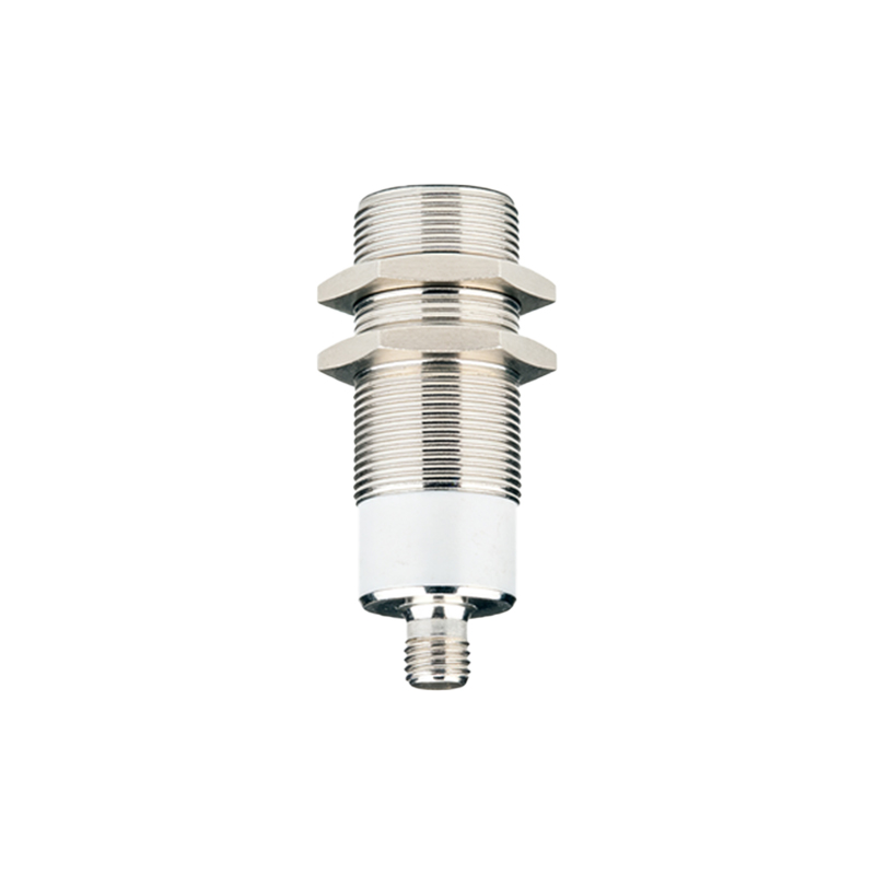
Every proximity sensor has a connection diagram, usually found on its body or in the manual. For a standard 3-wire DC sensor, the terminals are:
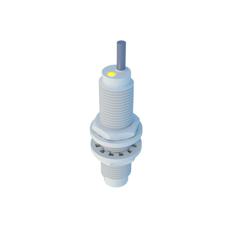
• Brown (or Red): This wire connects to the positive supply voltage (+V).
• Blue (or Black): This wire connects to the negative supply voltage or common (0V).
• Black (or White): This is the output signal wire. Its function depends on whether the sensor is PNP (sourcing) or NPN (sinking).
A 4-wire DC sensor often includes a second, complementary output wire. For 2-wire AC sensors, the terminals are simply for Line and Load. The output configuration—Normally Open (NO) or Normally Closed (NC)—determines the signal state when a target is detected. Understanding these labels is the foundation for correct installation.
Wiring a 3-Wire DC PNP Proximity Sensor
A PNP sensor sources current to the load. Follow this step-by-step process:
1. Power Connection: Connect the Brown wire to the positive terminal of your DC power supply (e.g., +24V).
2. Common Connection: Connect the Blue wire to the negative terminal (0V) of the power supply.
3. Load Connection: Connect the Black (output) wire to one terminal of your load (e.g., a PLC input, relay coil, or indicator light).
4. Completing the Circuit: Connect the other terminal of the load back to the power supply's negative (0V) terminal.
When a metal target enters the sensing range, the PNP switch closes internally, sourcing positive voltage from the Brown wire through the Black wire to the load, thereby activating it. The diagram below illustrates this configuration: [Imagine a diagram here showing a DC power supply, the sensor with Brown/+V, Blue/0V, Black/Out, and a load connected between Black and 0V].
Wiring a 3-Wire DC NPN Proximity Sensor
An NPN sensor sinks current from the load. The wiring is similar but with a key difference in the load connection:
1. Power Connection: Connect the Brown wire to the positive terminal of your DC power supply (+V).
2. Common Connection: Connect the Blue wire to the negative terminal (0V) of the power supply.
3. Load Connection: Connect one terminal of your load to the positive supply (+V).
4. Output Connection: Connect the other terminal of the load to the Black (output) wire of the sensor.
In this setup, when activated, the NPN switch closes internally, providing a path for current to flow from the load, through the Black wire, to the Blue wire (0V), thus completing the circuit and activating the load. The diagram below shows this sinking configuration: [Imagine a diagram here showing the load connected between +V and the sensor's Black wire, with Blue to 0V and Brown to +V].
Wiring a 2-Wire AC Proximity Sensor
AC sensors are simpler to wire but require attention to voltage ratings.
1. Identify Terminals: The two wires are typically not color-coded but labeled as L1 (or 1) and L2 (or 2).
2. Series Connection: Connect one terminal (L1) to the AC line voltage (e.g., 120V AC).
3. Load Connection: Connect the other terminal (L2) to one side of your load.
4. Neutral Completion: Connect the other side of the load to the neutral wire of the AC supply.
The sensor acts as a