Understanding the Fundamentals of 3-Wire Proximity Sensors
In industrial automation and control systems, 3-wire proximity sensors are ubiquitous components for non-contact detection of metallic objects. Unlike their 2-wire counterparts, these sensors offer superior performance, stability, and diagnostic capabilities, making them the preferred choice for demanding applications. The core principle involves an oscillator circuit that generates a high-frequency electromagnetic field from the sensor's face. When a metallic target enters this field, it induces eddy currents, causing a change in the oscillator's amplitude. This change is detected by a threshold circuit, which then switches the output state. The "3-wire" designation is crucial, as it refers to the distinct power, ground, and signal wires, enabling a clear separation of the supply and load circuits. This architecture is fundamental to their reliable operation and forms the basis for the standard wiring configurations discussed in this guide.
Decoding the Wire Color Standards and Functions
A critical step before connecting any sensor is correctly identifying its wires. While standards can vary slightly by manufacturer and region (IEC vs. NEMA), a common color code is widely adopted for DC-powered 3-wire sensors. The brown wire is universally designated for the positive supply voltage (+V). The blue wire is consistently used for the ground or common negative (0V). The output signal wire color indicates its switching function: a black wire typically denotes a normally open (NO) output, while a white wire often signifies a normally closed (NC) output. Some sensors may combine these, featuring both a black (NO) and a white (NC) wire, effectively making it a 4-wire device. Always, without exception, consult the specific sensor's datasheet or manual for the definitive wiring information, as deviations exist. Misidentification can lead to incorrect operation or permanent damage to the sensor or the controller.
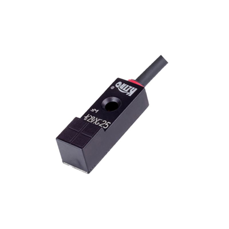
Wiring Diagram for an NPN Sinking Output Sensor
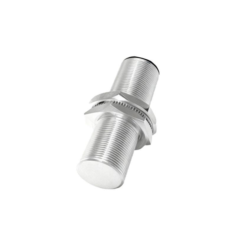
The NPN type is one of the two primary output configurations. In an NPN sensor, the output switching device is an NPN transistor. The emitter of this transistor is internally connected to the blue (0V) wire. When the sensor is active (target detected), the transistor turns on, effectively connecting the black output wire to the blue wire (0V). This configuration is known as "sinking" because the output acts as a path to ground for the load current. The standard wiring diagram is as follows: Connect the brown wire to the positive DC supply (e.g., +24VDC). Connect the blue wire to the negative/ground of the same supply. The black (NO) output wire is connected to one side of the load (e.g., a PLC input module). The other side of the load must then be connected to the positive supply voltage. When the sensor activates, it completes the circuit by sinking current from the load to ground, signaling the detection event.
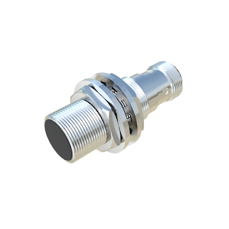
Wiring Diagram for a PNP Sourcing Output Sensor
Conversely, the PNP sensor uses a PNP transistor for its output stage. Here, the emitter is internally connected to the brown (+V) wire. Upon activation, the transistor switches on, connecting the black output wire to the positive supply voltage. This is termed a "sourcing" output, as it provides a source of current to the load. The wiring for a PNP sensor differs accordingly: The brown wire connects to positive DC supply, and the blue wire to supply ground, as before. The critical difference lies in the load connection. The black (NO) output wire is connected to one side of the load. The other side of the load must be connected to the ground/negative terminal of the power supply. Thus, when the sensor activates, it sources current from the positive supply, through the sensor's output, to the load, and then to ground. This configuration is prevalent in European and many modern global systems.
Connecting to a Programmable Logic Controller (PLC)
Integrating a 3-wire proximity sensor with a PLC is a common task. The process depends entirely on the PLC input module's type (sinking or sourcing) and the sensor's output type (NPN or PNP). For a sinking PLC input module (which expects a positive voltage to be presented to it), you must use a PNP (sourcing) sensor. The sensor's black wire connects to the PLC input terminal, and the PLC input's common is wired to ground. For a sourcing PLC input module (which provides a positive voltage and expects a path to ground), you must use an NPN (sinking) sensor. The sensor's black wire connects to the PLC input, and the PLC input's common is wired