Understanding Photoelectric Sensor Basics
A 24V DC photoelectric sensor is a cornerstone of modern industrial automation, used for detecting the presence, absence, or position of objects without physical contact. It operates by emitting a beam of light (visible red, infrared, or laser) and detecting changes in the received light intensity. The 24V DC power specification is the industry standard for factory automation controls, compatible with Programmable Logic Controllers (PLCs) and other control systems. Before beginning any wiring procedure, it is paramount to consult the specific sensor's datasheet for its exact electrical characteristics, terminal designations, and housing type. Always ensure the power is locked out and tagged out (LOTO) before handling any electrical connections to prevent injury or equipment damage.
Components and Wiring Terminology
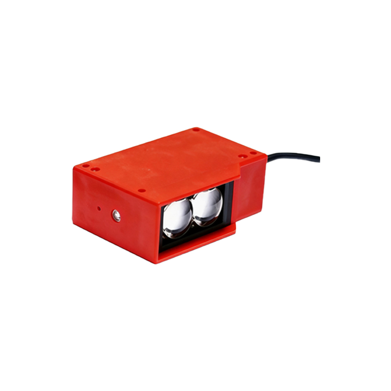
A typical three-wire 24V DC photoelectric sensor will have the following connections: Brown wire (or labeled L+ or +V): This is the positive power supply input, typically connected to the 24V DC positive terminal. Blue wire (or labeled L- or 0V): This is the negative power supply input or common, connected to the 24V DC negative terminal. Black wire (or labeled OUT or LOAD): This is the switched output signal wire. The nature of this output—sourcing (PNP) or sinking (NPN)—determines the wiring configuration to the load. The sensor housing also includes indicators: a power (PWR) LED and an output activation (ACT) LED, which are crucial for troubleshooting.
Wiring a Sourcing (PNP) Sensor Configuration
In a PNP (sourcing) configuration, the sensor's output switch connects the load to the positive supply voltage when active. To wire it, first connect the brown wire to the +24V DC power supply terminal. Next, connect the blue wire to the 0V (common) terminal of the same power supply. The black output wire is then connected to one side of your load device (e.g., a PLC digital input module). The other side of the load device must be connected back to the 0V (common) terminal. In this setup, when the sensor detects an object, it internally connects the black wire to the internal +24V, "sourcing" current through the load to common, thus activating the PLC input.
Wiring a Sinking (NPN) Sensor Configuration
In an NPN (sinking) configuration, the sensor's output switch connects the load to the common (0V) when active. The power connections remain identical: brown to +24V and blue to 0V. The critical difference is in the output circuit. Connect the black output wire to one side of your load. The other side of the load must now be connected to the +24V supply. When the sensor activates, it internally connects the black wire to the internal 0V, "sinking" current from the load, which is powered by +24V, down to common. This completes the circuit and signals the PLC. It is essential to match the sensor's output type (PNP/NPN) with the input circuit requirements of your controller.
Connecting to a PLC Digital Input Module
Most PLC digital input (DI) modules are designed to work with either PNP or NPN sensors, but their internal circuitry differs. A typical "sinking" DI module has its internal circuitry connected to +24V, expecting a connection to 0V from the sensor to activate; this requires a PNP sensor. Conversely, a "sourcing" DI module has its internal circuitry connected to 0V, expecting a connection to +24V from the sensor; this requires an NPN sensor. Always verify your PLC module's manual. The wiring involves connecting the sensor's black wire to the specific DI point and ensuring the sensor's power common (blue wire) and the PLC module's common terminal are connected to the same 0V reference point to avoid ground loops.
Two-Wire AC/DC Sensor Wiring
Some photoelectric sensors are two-wire devices, designed to be connected in series with the load, similar to a mechanical switch. They can often operate on a wide voltage range (e.g., 20-250V AC/DC). Wiring is simpler: one wire connects to the positive or live side of the power supply, and the other wire connects to one side of the load. The other side of the load connects back to the negative or neutral side of the supply. A key consideration with two-wire sensors is the residual leakage current (a few mA) when in the "off" state, which may be enough to weakly activate a high-impedance PLC input. A bypass resistor may be required per the sensor and PLC manuals.
Shielded Cable and Noise Immunity
In electrically noisy industrial environments, proper shielding is critical for reliable sensor operation. Many sensor cables come with an external braided or foil shield. This shield should be connected to a functional earth ground at one end only, typically at the control panel end, to prevent ground loops. Connect the drain wire of the shielded cable to the PE (Protective Earth) or ground terminal in the cabinet. Keep sensor cables away from high-voltage power lines, motor drives (VFDs), and welding equipment. Using conduit provides additional physical and some electromagnetic protection. Proper grounding of the sensor's metal housing, if applicable, is also recommended.
Testing and Troubleshooting Steps
After wiring, apply power systematically. First, check that the sensor's power (PWR) LED illuminates. If it does not, verify the voltage at the sensor terminals with a multimeter, checking for correct polarity and voltage level (approximately 24V DC). If power is correct but the LED is off, the sensor may be faulty. Next, test the sensing function. Trigger the sensor (e.g., place an object in the beam) and observe the output (ACT) LED. It should change state. Simultaneously, measure the voltage between the black output wire and the blue common wire. For a PNP sensor, it should switch from near 0V to near 24V when activated. For an NPN, it should switch from near 24V to near 0V. If the output LED works but the signal does not reach the PLC, check the load wiring and the PLC input's status indicators.