Introduction to Photoelectric Sensors
Photoelectric sensors are essential components in industrial automation, widely used for object detection, positioning, and counting. These devices operate by emitting a light beam—typically infrared, visible red, or laser—and detecting changes in the received light caused by the presence or absence of an object. The performance and suitability of a photoelectric sensor heavily depend on its specifications and physical dimensions, which must align with the application's environmental and spatial constraints. Understanding these parameters ensures reliable operation in diverse settings, from factory floors to clean rooms.
Key Specifications Overview
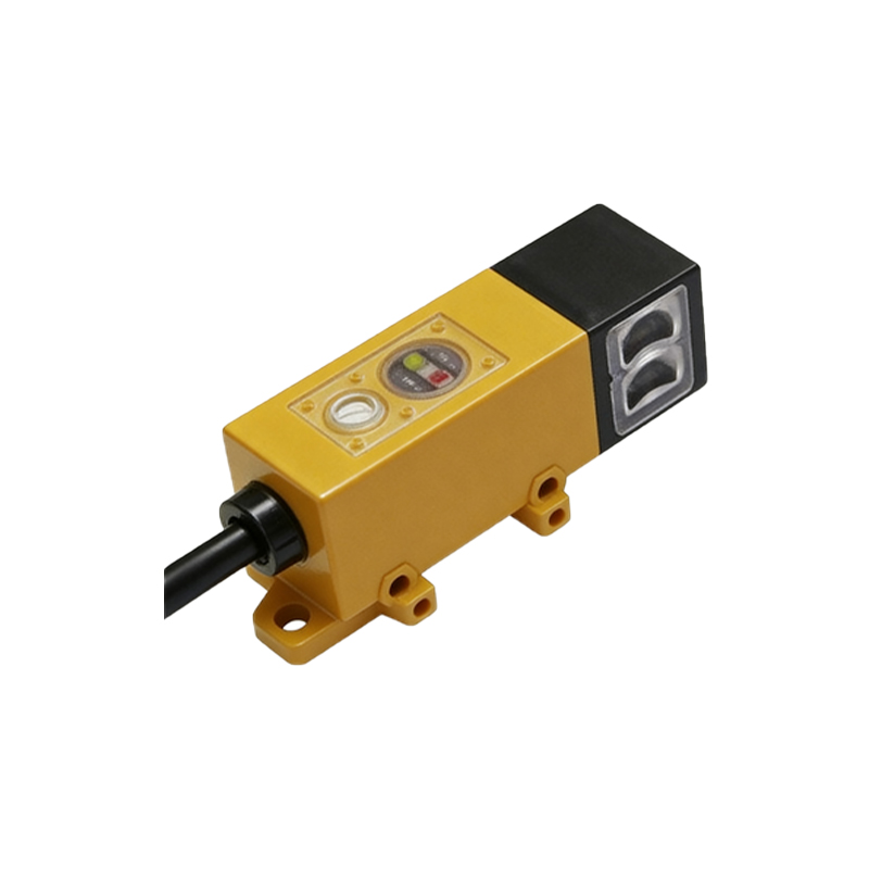
The core specifications of photoelectric sensors include sensing range, response time, light source type, and output configuration. Sensing range defines the maximum distance at which the sensor can reliably detect an object, varying from a few millimeters to several meters depending on the model. Response time, measured in milliseconds, indicates how quickly the sensor reacts to changes, critical for high-speed applications. Common light sources are LED-based (infrared or visible) for general use or laser for precise, long-range detection. Outputs typically consist of NPN/PNP transistors or relay contacts, interfacing with PLCs or other control systems. Additional specs like switching frequency, ambient temperature tolerance, and protection ratings (e.g., IP67) also impact selection.
Standard Dimensions and Form Factors
Photoelectric sensors come in various form factors, categorized mainly by housing shape and size. Cylindrical sensors are common, with diameters ranging from M8 (8mm) to M30 (30mm) and lengths from 40mm to 80mm, suitable for compact installations. Rectangular or block-style sensors offer larger sensing ranges and often include adjustable brackets, with typical dimensions around 50mm x 30mm x 20mm. Miniature sensors, as small as 4mm x 6mm x 12mm, are designed for tight spaces. Each form factor includes mounting threads or holes, with M8, M12, and M18 being standard thread sizes for cylindrical types. Proper dimension matching ensures easy integration into machinery without interference.
Through-Beam vs. Reflective Sensors
Dimensions and specs differ significantly between through-beam and reflective (retro-reflective or diffuse) sensors. Through-beam sensors consist of separate emitter and receiver units, each typically cylindrical with M12 or M18 threads, requiring alignment over distances up to 20 meters. Their housing lengths often exceed 60mm to accommodate robust optics. Reflective sensors combine emitter and receiver in a single housing, usually block-shaped or cylindrical with sizes like 30mm x 40mm x 15mm for diffuse types. Retro-reflective models may be slightly larger due to polarized filters. Sensing ranges are shorter for reflective types, generally under 5 meters, impacting the required lens size and housing depth.
Environmental and Mounting Considerations
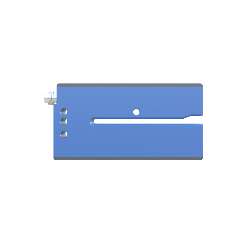
Specifications must account for environmental factors, which influence dimensions. For harsh conditions, sensors feature rugged housings with increased size for sealing (e.g., IP69K ratings), often adding 10-20% to standard dimensions. Temperature-resistant models may include heat sinks, extending length. Mounting options like brackets or slots affect overall footprint; adjustable brackets add 15-30mm to width or height. In dusty or wet areas, sensors with built-in air purge ports require extra space, typically widening the housing by 5-10mm. Always verify clearance for wiring connectors, as M12 connectors add roughly 15mm to the sensor's rear profile.
Industry Standards and Compliance
Compliance with international standards shapes sensor dimensions and specs. IEC 60947-5-2 outlines performance and safety requirements, influencing housing design for electrical isolation. EN 61131-2 defines form factors for PLC compatibility, standardizing thread sizes and mounting patterns. For food or pharmaceutical applications, FDA-compliant materials may alter dimensions due to smoother, crevice-free surfaces. CE and UL certifications often require additional internal spacing for component insulation, slightly increasing housing size. These standards ensure interoperability but mandate careful review of datasheet dimensions before installation.
Selecting the Right Sensor for Your Application
To choose a photoelectric sensor, start by assessing the detection distance and object size, which dictate sensing range and lens diameter—larger lenses often mean bigger housings. Next, consider response time needs; faster sensors may have compact electronics but require adequate heat dissipation, affecting length. Environment dictates protection ratings, with IP67 or higher adding bulk. Finally, measure available space: for narrow gaps, opt for miniature cylindrical sensors (e.g., M8), while open areas allow block-style units. Always cross-reference specs like operating voltage (10-30V DC common) and output type with your system, and consult manufacturer datasheets for exact dimensions, as even similar models can vary by 1-2mm.
Future Trends in Sensor Design
Advancements are driving smaller, more efficient photoelectric sensors without compromising specs. Micro-optics and SMD components enable reductions in housing size, with new models under 10mm in diameter. Integrated IO-Link communication adds smart features but may slightly increase length for circuitry. Energy-efficient LEDs allow compact power supplies, shrinking overall form factors. However, trade-offs exist: ultra-miniature sensors might have shorter ranges or lower durability. As Industry 4.0 evolves, expect standardized compact designs with enhanced specs, like longer ranges in smaller packages, but always verify dimensions for retrofit compatibility.