Introduction to 3-Wire Proximity Switches for Liquid Level Sensing
In industrial automation and process control, accurately monitoring liquid levels is a fundamental requirement. Among the various technologies employed, the 3-wire proximity switch stands out for its reliability and versatility. Unlike mechanical float switches, these solid-state sensors operate without physical contact with the liquid, using electromagnetic fields to detect the presence or absence of a target, typically a float or a conductive material. The "3-wire" designation refers to the standard wiring configuration: one wire for power supply, one for ground, and one for the switched output signal. This design offers significant advantages over 2-wire versions, including better switching performance, lower leakage current, and the ability to handle higher loads directly. Engineers favor them for applications involving water, oils, coolants, and various chemicals where durability and precise point-level detection are critical.
Core Operating Principles and Internal Circuitry
The operation of a 3-wire inductive or capacitive proximity switch for liquid level control hinges on its internal oscillator circuit. In a typical setup, a float containing a magnet or a metallic flag acts as the target. For inductive sensors, when this metallic target enters the sensor's electromagnetic field, it causes eddy currents that dampen the oscillator's amplitude. This change is detected by a threshold circuit, which triggers a solid-state switch (usually a transistor) in the output stage. Capacitive sensors work on a similar principle but detect changes in capacitance caused by the presence of a liquid or a float, making them suitable for non-metallic tank materials. The key differentiator of the 3-wire system is its separate power and output lines. This allows for a dedicated output transistor (PNP or NPN sourcing/sinking) that provides a clean, discrete ON/OFF signal to a Programmable Logic Controller (PLC), relay, or indicator lamp, independent of the sensor's internal power consumption.
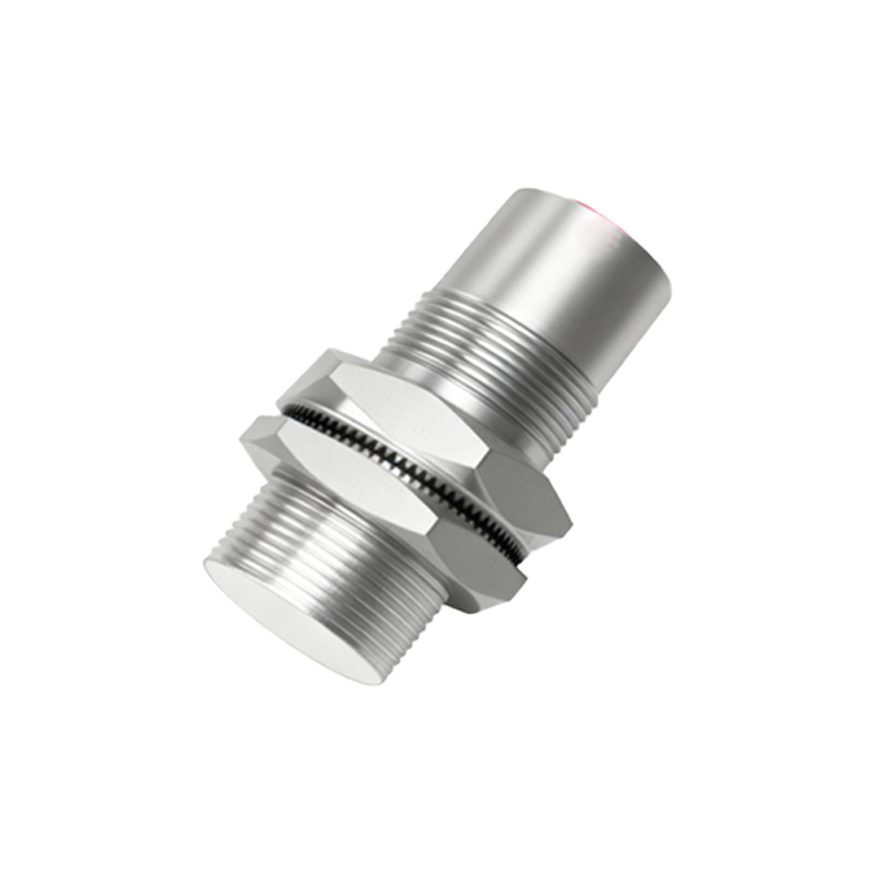
Wiring Configurations: PNP vs. NPN Outputs
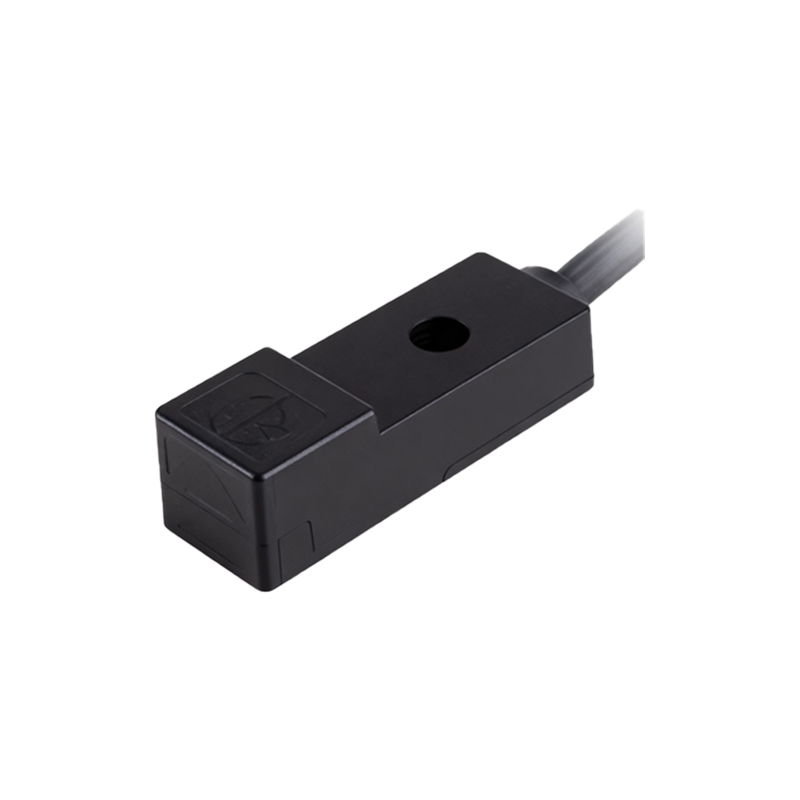
A crucial aspect of applying 3-wire sensors is understanding the two primary output types: PNP (sourcing) and NPN (sinking). This choice is dictated by the control system's input module requirements. A PNP sensor switches the positive voltage to the load. In its wiring, the brown wire (typically) connects to DC+, the blue wire to DC-, and the black wire is the switched positive output. When activated, the black wire "sources" current to the PLC input. Conversely, an NPN sensor switches the negative or ground side. Here, the black wire is the switched negative output; when active, it "sinks" current from the PLC input to ground. Selecting the wrong type for a given PLC input will result in a non-functional circuit. Engineers must carefully consult datasheets and system diagrams to ensure compatibility, as the physical connectors are often identical.
Key Advantages in Industrial Applications
The 3-wire design confers several operational benefits essential for robust liquid level control. First, they exhibit minimal leakage current (often less than 1.8 mA), which prevents false triggering in sensitive PLC inputs or when controlling small relays. Second, they offer superior switching speed and frequency response compared to 2-wire AC/DC sensors, suitable for fast-paced processes. Third, the ability to directly interface with low-power control devices without an intermediate relay simplifies panel design and reduces costs. Their solid-state construction ensures a long operational life with no moving parts to wear out, even in applications with vibration, foam, or turbulent liquid surfaces. Furthermore, many models feature LED status indicators for easy diagnostics and are housed in rugged, sealed enclosures (e.g., IP67, IP69K) for use in wet, dusty, or washdown environments common in food & beverage, pharmaceutical, and chemical processing.
Installation, Calibration, and Troubleshooting Tips
Proper installation is paramount for reliable operation. Sensors must be mounted securely at the desired detection point, considering the material of the tank wall and the specific sensing distance (Sn). For metallic tanks, non-flush mountable sensors may be required to avoid interference from the surrounding metal. Calibration typically involves adjusting the sensor's sensitivity potentiometer (if available) to ensure stable switching of the target float while ignoring the tank structure or liquid turbulence. Common troubleshooting steps include verifying power supply voltage, checking for correct wiring (PNP vs. NPN), inspecting for accumulated debris on the sensing face, and ensuring the target is within the specified switching range. Using a multimeter to measure the output voltage in active and inactive states quickly isolates sensor faults from control system issues.
Selection Criteria for Optimal Performance
Choosing the