Understanding the 4-Channel Photoelectric Sensor
A 4-channel photoelectric sensor is a sophisticated industrial device designed to detect the presence, absence, or position of objects using four independent sensing beams. Unlike single-channel sensors, this configuration allows for multi-point monitoring within a single compact housing, significantly enhancing system efficiency and reducing installation complexity. Each channel typically consists of its own emitter and receiver pair, operating on principles such as through-beam, retro-reflective, or diffuse reflection. These sensors are fundamental in automation applications like packaging, material handling, and assembly lines, where precise, simultaneous detection at multiple points is critical. Understanding the internal architecture—where four distinct circuits operate in parallel—is the first step toward a successful wiring installation.
Essential Tools and Safety Precautions
Before commencing any wiring work, gather the necessary tools and prioritize safety. You will require a set of insulated screwdrivers, wire strippers, crimping tools, appropriate ferrules for stranded wires, a digital multimeter for continuity and voltage checks, and the sensor's datasheet. Always disconnect all power sources to the control cabinet and the sensor itself. Verify the absence of voltage using the multimeter. Wear appropriate personal protective equipment (PPE) such as safety glasses and insulated gloves. Ensure the work environment is dry and well-lit. Carefully review the manufacturer's wiring diagram, as pin assignments and voltage requirements can vary between models and brands. Never assume compatibility; incorrect wiring is a leading cause of sensor failure.
Deciphering the Wiring Diagram and Pin Configuration
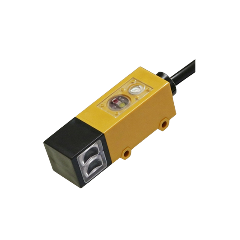
The manufacturer's datasheet provides the critical wiring diagram. A standard 4-channel sensor with a multi-pin connector (often M12 or M8) will have pins designated for power supply, ground, and the output signals for each channel. A common configuration for a PNP (sourcing) sensor is: Pin 1: +V (e.g., 10-30V DC), Pin 2: 0V (Ground), Pin 3: Channel 1 Output, Pin 4: Channel 2 Output, Pin 5: Channel 3 Output, Pin 6: Channel 4 Output. For NPN (sinking) sensors, the output logic is reversed. Some sensors may have a shared common pin or separate diagnostic outputs. It is imperative to identify whether your sensor is PNP or NPN, as this must match the input type of your programmable logic controller (PLC) or relay module. Mismatching can lead to malfunction or damage.
Step-by-Step Wiring Procedure for Standard DC Sensors
Begin by preparing the cables. Use shielded, multi-conductor cable suitable for industrial environments. Strip the wire ends neatly and apply ferrules for a secure, reliable connection in the terminal block. First, connect the power supply. Route the positive DC wire (+V) to the designated voltage pin (e.g., Pin 1) and the negative or 0V wire to the ground pin (e.g., Pin 2). Ensure these connections are tight and correct; reversed polarity can instantly destroy the sensor's electronics. Next, connect the output wires. For each channel (e.g., Pins 3, 4, 5, 6), run a separate wire to the corresponding digital input on your PLC. For a PNP sensor, each output wire will supply voltage to the PLC input when the respective channel detects an object. Always maintain consistent color coding (e.g., brown for +V, blue for 0V, black/white/gray for outputs) as per international standards.
Connecting to PLCs and Control Systems
Integration with a PLC is the final objective. On the PLC side, each sensor channel wire connects to a discrete DC input point. Most PLC input cards require the completion of a circuit: for a PNP sensor, the PLC input common is connected to 0V. When the sensor activates, it sources current to the PLC input. For an NPN sensor, the PLC input common is connected to +V, and the sensor sinks current to ground. It is crucial to verify the PLC's input circuit specifications. Some systems may require external pull-up or pull-down resistors, though modern sensors often have this built-in. Within the PLC programming software, you will then address these input points (e.g., I0.0, I0.1, I0.2, I0.3) to create logic for controlling machinery, counting, or sorting based on the sensor's state.
Testing, Troubleshooting, and Best Practices
After wiring, do not immediately power the entire system. First, apply power only to the sensor and observe its indicator LEDs. Most 4-channel sensors have separate LEDs for power and for each channel's output status. Use a test object to trigger each channel individually and confirm the corresponding LED illuminates. Then, use your multimeter to check the voltage at each output pin relative to ground during activation and deactivation. Finally, power the PLC and monitor the input status bits on its software or hardware indicators. Common issues include no response (check power and polarity), only some channels working (check individual wire continuity and PLC input health), or erratic behavior (often caused by electrical noise—ensure proper shield grounding at the control panel end only). For long-term reliability, secure cables in cable ducts, avoid running sensor wires parallel to high-power cables, and adhere to the specified operating voltage range.