Understanding the Fundamentals of Sensing Distance
The nominal sensing distance (Sn) of a proximity sensor is a key parameter defined under specific standardized conditions, typically involving a standard target. It is crucial to understand that this is a theoretical value. The effective or real sensing distance (Sr) can vary due to factors like temperature fluctuations, supply voltage tolerance, and target material properties. For instance, a sensor rated for 10mm (Sn) might have an assured operating distance (Sa) of 0 to 8.1mm, which accounts for these industrial variances. The concept of the hysteresis zone is also vital; it prevents output chattering when a target is at the exact threshold by creating a differential between the switch-on and switch-off points. This fundamental understanding is the bedrock of effective adjustment.
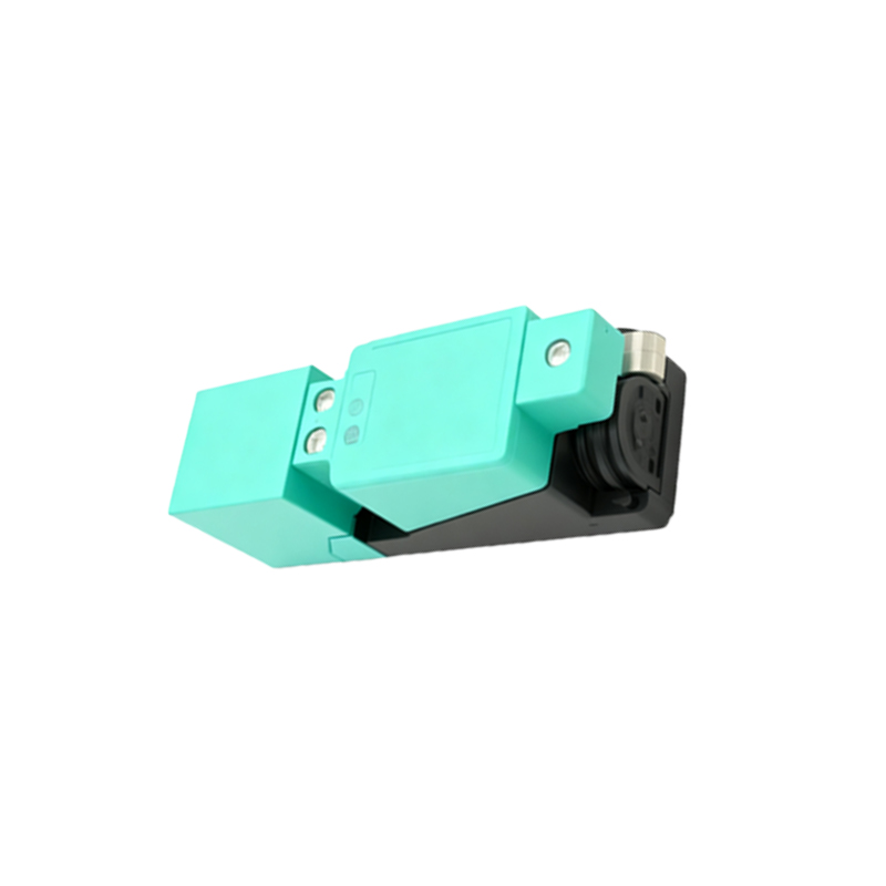
Primary Adjustment Methods and Mechanisms
Most modern proximity sensors offer one or more methods for fine-tuning the sensing range. The most common is a built-in potentiometer, accessible via a small screw slot on the sensor body. Rotating this potentiometer alters the sensitivity of the internal oscillator or amplifier circuit, thereby increasing or decreasing the effective sensing distance. Another method involves teach-in or programming buttons, often found on intelligent or IO-Link enabled sensors. By pressing a sequence of buttons (e.g., pressing when the target is at the desired maximum distance), the sensor learns and sets its new operational threshold. Some specialized sensors may also feature DIP switches or software-based configuration via a connected PLC or configuration tool for multi-point adjustment.
Factors Influencing Real-World Sensing Distance
Successful adjustment requires accounting for environmental and target-specific factors. The target material is paramount; ferrous metals (like mild steel) provide the nominal Sn, while non-ferrous metals (aluminum, brass) and stainless steel significantly reduce the effective range, often requiring a correction factor (e.g., 0.4 for aluminum). The target size and shape also matter; a target smaller than the sensor's face will reduce Sr. Environmental conditions such as extreme ambient temperatures can affect electronic component performance, and the presence of adjacent metal objects or other sensors can cause mutual interference (shielding or electromagnetic influence), necessitating increased mounting distances or shielding.
Step-by-Step Procedure for Optimal Adjustment
A systematic approach ensures reliable setup. First, mount the sensor securely. Second, connect it to the specified power supply within its voltage tolerance. Third, introduce the correct standard target (usually a 1mm thick square of mild steel with sides equal to the sensor's diameter or 3x Sn). Fourth, with no target present, use a non-metallic tool to adjust the potentiometer counter-clockwise to minimum sensitivity. Fifth, slowly bring the target towards the sensor face along the axis. Sixth, at the desired operational position, adjust the potentiometer clockwise until the output indicator (LED) just activates. Seventh, slowly withdraw the target and verify the switch-off point, noting the hysteresis. Finally, test the setup with the actual application target under normal operating cycles to ensure consistency and avoid nuisance tripping.
Troubleshooting Common Adjustment Issues
Several issues can arise post-adjustment. If the sensor cannot achieve the required distance, verify the target material and size, check for nearby interfering metals, and ensure the power supply is adequate. Erratic switching or chattering often indicates excessive sensitivity; reduce it slightly and check for mechanical vibration of the target or sensor. A sensor that will not adjust at all may have a damaged potentiometer or internal circuit failure. Always refer to the manufacturer's datasheet for specific correction factors, temperature ratings, and recommended mounting distances between multiple sensors. For embedded or hard-to-reach sensors, using an extension cable with a remote potentiometer or utilizing software configuration is recommended.
Advanced Considerations and Best Practices
For critical applications, consider sensors with built-in diagnostics or IO-Link communication. These can provide real-time data on signal strength, temperature, and operating distance margin, enabling predictive maintenance. When adjusting for a non-standard target, it is best practice to set the sensitivity using the actual target material. Always leave a safety margin (typically 20-30% of Sa) to account for mechanical wear, buildup of contaminants (like metal chips or oil), and long-term component drift. Document the adjustment settings, especially in multi-sensor systems, to facilitate faster maintenance. Regular verification of the sensing distance as part of preventive maintenance schedules helps prevent unplanned downtime.