Understanding Photoelectric Sensor Polarity
Photoelectric sensors are fundamental components in industrial automation, used for detection, counting, and positioning. A common question among technicians and engineers is whether reversing the electrical power connections—connecting the positive and negative wires incorrectly—can cause permanent damage or "burn out" the sensor. The answer is not a simple yes or no, as it depends heavily on the sensor's internal design and protection circuitry. Modern photoelectric sensors typically incorporate several protective features, but understanding the underlying electronics is crucial for proper installation and troubleshooting. This article explores the technical aspects of polarity, potential failure modes, and best practices to prevent damage.
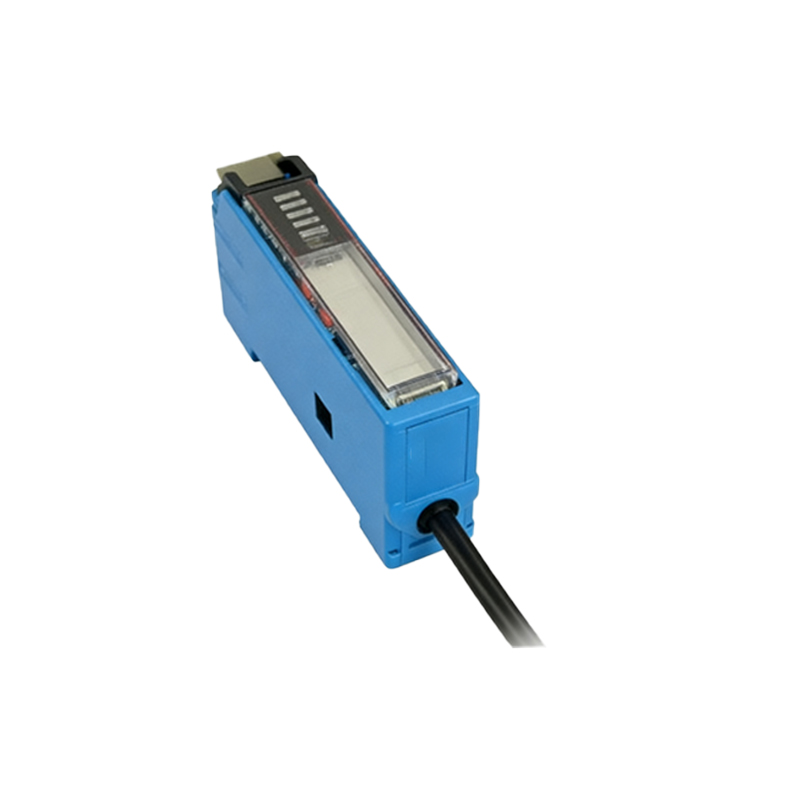
Internal Circuit Design and Protection Mechanisms
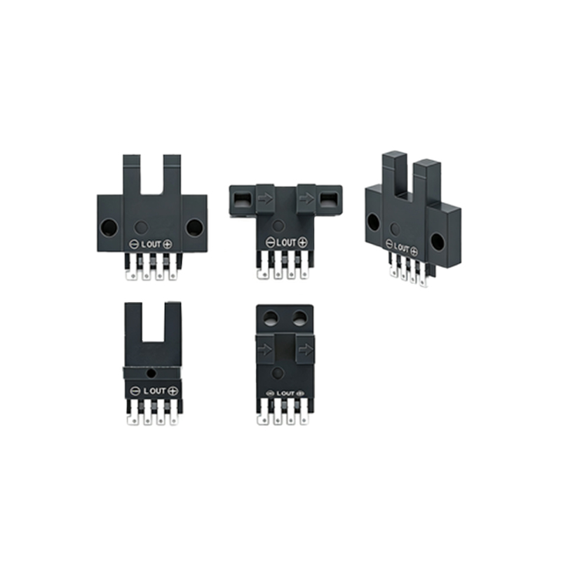
Most contemporary DC-powered photoelectric sensors are designed with polarity protection. This is often achieved through a series diode or a bridge rectifier circuit at the power input stage. A series diode only allows current to flow when the polarity is correct, effectively blocking reverse current. A bridge rectifier automatically corrects the polarity, meaning the sensor will function normally regardless of how the two power wires are connected. These are passive protections. Additionally, many sensors include active protection like transient voltage suppression (TVS) diodes, fuses, or resettable fuses (PTCs) that guard against over-voltage and over-current conditions, which might occur during a miswiring event alongside other faults.
Potential Risks of Reverse Polarity Connection
Despite built-in protections, reversing polarity can still pose risks, especially in older, simpler, or very low-cost sensor models that may lack robust protection. If a sensor relies solely on a series diode for protection and that diode fails, reverse voltage could reach sensitive internal components like the integrated circuit (IC), light-emitting diode (LED), or phototransistor. This can cause immediate failure. Furthermore, if the reverse connection is made while the sensor is under load or in a faulty state, it might create a short circuit, leading to excessive current that could overwhelm any fuse or protection device, resulting in permanent damage to the sensor or even the power supply.
AC-Powered Sensors and Output Signal Wiring
The discussion primarily applies to DC sensors. For photoelectric sensors powered by alternating current (AC), polarity is not applicable to the power terminals, as AC voltage constantly reverses. However, miswiring the load (the device controlled by the sensor's output) remains a critical concern. Connecting a load incorrectly to a sensor's output contacts, especially with solid-state outputs, can cause a short circuit when the output activates. Always refer to the wiring diagram for the specific output type (PNP/NPN sourcing/sinking, relay contact) and ensure the load is connected in series with the correct polarity relative to the power supply.
Diagnosing Sensor Failure After a Wiring Error
If a sensor fails to operate after installation, and reverse polarity is suspected, follow a systematic approach. First, disconnect power and verify the wiring against the manufacturer's datasheet. Use a multimeter to check for correct supply voltage at the sensor's terminals. If the sensor has polarity protection like a bridge rectifier, simply correcting the wires should restore function. If it does not, the sensor may have sustained damage. Internal damage from reverse polarity often affects the power regulation section or the core sensing element, rendering the sensor unresponsive or causing erratic behavior that cannot be resolved by external adjustments.
Best Practices for Installation and Prevention
To entirely avoid the risk of damage from incorrect wiring, adhere to strict installation protocols. Always de-energize the circuit before making connections. Meticulously follow the wiring diagram provided on the sensor's label or in its documentation, paying close attention to color codes (typically brown for +V, blue for 0V/negative, and black for the output signal). Implement clear labeling on control panel wires. For critical applications, consider using sensors with explicit reverse polarity protection stated in their specifications and utilize pre-made, molded connector cables when available to eliminate termination errors. Regular training for maintenance personnel on these fundamentals is invaluable.
Conclusion and Key Takeaways
In summary, while many modern photoelectric sensors are equipped with circuitry to withstand a reverse polarity connection, it is not a guaranteed feature and should never be relied upon as a standard practice. The risk of damage, though mitigated by technology, remains real and depends on the specific sensor's design. The most reliable method to prevent sensor failure is correct installation based on manufacturer guidelines. Treating polarity with care ensures sensor longevity, reduces downtime, and maintains the efficiency and safety of automated systems. When in doubt, always consult the product manual before applying power.