Understanding Proximity Sensors and Their Outputs
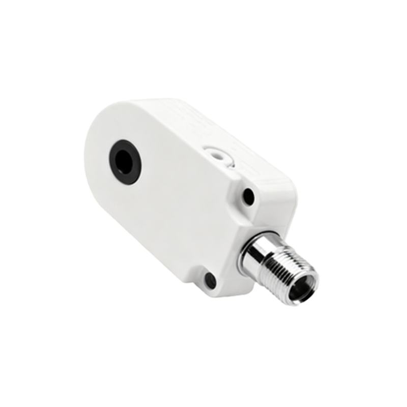
Proximity sensors are fundamental components in modern industrial automation, providing non-contact detection of metallic or other objects. They operate on various principles, including inductive, capacitive, and magnetic technologies, with inductive sensors being the most common for metal detection. The primary function of a proximity sensor is to detect the presence or absence of a target within its sensing range and convert this physical event into an electrical signal. Typically, these sensors provide a digital output, which is either a switching signal (ON/OFF) or a change in state of a solid-state switch. The most common output configurations are NPN (sinking) and PNP (sourcing) transistor outputs. Understanding the sensor's datasheet, including its output type, voltage rating, and current capacity, is the critical first step before interfacing it with any other control component like a relay.
The Role of Intermediate Relays in Control Circuits
An intermediate relay, also known as an auxiliary or control relay, acts as an amplifying interface between a low-power control signal and a higher-power load. While a proximity sensor can switch a small amount of current directly, many industrial loads—such as contactor coils, solenoid valves, or indicator lamps—require higher currents or operate at different voltage levels than the sensor's output can handle. This is where the intermediate relay becomes indispensable. It uses the sensor's modest switching signal to energize its own coil, which in turn closes or opens heavier-duty contacts capable of handling the main load current. This setup provides electrical isolation, protects the sensitive sensor electronics from load-side transients, and allows for signal multiplication (one sensor controlling multiple circuits via the relay's contacts).
Wiring Configurations: NPN vs. PNP Sensors
The wiring diagram differs significantly based on whether an NPN or PNP proximity sensor is used, and it must align with the relay coil's requirements. For a standard DC system using a PNP (sourcing) sensor, the sensor's output wire provides positive voltage when activated. This output wire is connected directly to one terminal of the relay coil. The other terminal of the relay coil is then connected to the DC common or negative rail. When the sensor detects an object, it sources current to the relay coil, energizing it. For an NPN (sinking) sensor, the output acts as a path to negative. Here, one side of the relay coil is connected to the positive supply, and the other side is connected to the sensor's output wire. When activated, the sensor sinks current from the relay coil to negative, completing the circuit. It is paramount to include a flyback diode (also known as a freewheeling or suppression diode) in reverse bias across the relay coil terminals to protect the sensor from voltage spikes generated when the coil de-energizes.

Practical Considerations for Reliable Operation
Several practical factors ensure long-term reliability in the field. First, always verify the voltage ratings: the sensor's supply voltage, the relay coil voltage, and the load voltage must be compatible. Mismatches can lead to failure or erratic operation. Second, consider the current ratings. The sensor's maximum switching current must not be exceeded by the inrush and holding current of the relay coil. Third, use proper wiring practices. Employ shielded cables for sensors in electrically noisy environments, grounding the shield at one end only. Keep sensor and power cables separated to avoid inductive coupling. Fourth, account for the relay's response time. The combined response time of the sensor and relay may introduce a slight delay, which must be acceptable for the application's timing requirements. Finally, implement diagnostic measures, such as pilot lights in parallel with the relay coil or sensor, to provide visual indication of circuit status for maintenance personnel.
Advanced Interfacing and Safety Notes
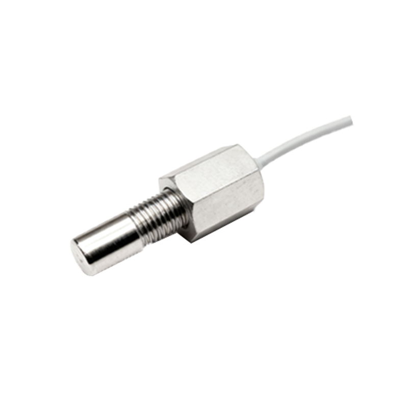
For more complex applications, interfacing modules or programmable logic controller (PLC) input cards can be used between the sensor and relay. These modules provide opto-isolation, signal conditioning, and conversion between different logic families. When designing safety-critical circuits, such as emergency stop functions, note that a standard proximity sensor and relay setup is not inherently fail-safe. Safety-rated devices and dedicated safety relays, which monitor for faults like welded contacts, are required for such applications. Always adhere to local and international electrical codes and standards (e.g., IEC, NEC) during panel design and installation. Proper labeling of all wires, terminals, and components is not just good practice; it is essential for troubleshooting and preventing hazardous mistakes during maintenance or modification.