Introduction to SN05-N Proximity Sensors
The SN05-N is a widely adopted inductive proximity sensor in industrial automation, known for its reliability in detecting metallic objects without physical contact. Its compact cylindrical design, typically M5 or M8 threaded barrel, makes it suitable for space-constrained applications. Proper installation is critical to ensure optimal sensing performance, longevity, and avoidance of false triggers. The mounting hole preparation directly influences the sensor's sensing range, stability, and resistance to environmental factors such as vibration or mechanical stress. This guide details the technical specifications and step-by-step procedures for correctly preparing and utilizing the mounting hole for the SN05-N sensor.
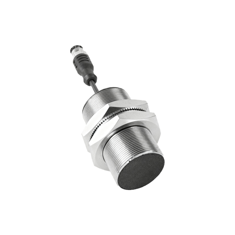
Mounting Hole Specifications and Tolerances
Accurate hole dimensions are paramount. For the standard SN05-N with an M8 thread, the recommended mounting hole diameter is 8.2 mm to 8.4 mm. This provides a slight clearance for easy insertion while ensuring sufficient thread engagement. The hole depth must exceed the sensor's threaded length by at least 1-2 mm to prevent bottoming out, which can damage the sensor or distort its housing. The hole should be drilled perpendicular to the mounting surface with a tolerance of ±0.5° to maintain the sensor's axial alignment. For flush-mount applications, the surrounding area must be free of ferromagnetic materials within 1.5 times the sensor's nominal sensing distance to prevent shielding effects. Non-ferromagnetic mounting brackets, such as those made from aluminum or stainless steel, are preferred when extended sensing ranges are required.
Step-by-Step Installation Procedure
Begin by verifying the sensor model and its corresponding thread size (e.g., M8 x 1.0). Select the appropriate drill bit and reamer to achieve the specified hole diameter with a smooth finish. Deburr the hole thoroughly to remove any sharp edges or metal shavings that could impair threading or damage the sensor's O-ring seal. Apply a moderate amount of thread-locking compound if vibration is a concern, but avoid contaminants on the sensor's sensing face. Hand-start the sensor into the hole to prevent cross-threading, then tighten using a calibrated torque wrench. The recommended tightening torque for an M8 SN05-N is typically 5-10 Nm. Over-tightening can crack the housing or deform threads, while under-tightening may lead to loosening under operational stress. Finally, ensure the sensing face is flush or slightly recessed as per the installation type (flush or non-flush).
Alignment and Sensing Distance Considerations
Correct alignment between the sensor's axis and the target object is crucial. The target should approach the sensing face perpendicularly for maximum reliability. For side-sensing applications, maintain a clearance of at least one sensor diameter between the mounting hole and adjacent structures to avoid lateral interference. The effective sensing distance (Sn) can be affected by the target material; steel targets achieve the rated distance (e.g., 2 mm for SN05-N), while aluminum or brass may reduce it by 30-60%. Always conduct a post-installation test with the actual target material under operational conditions. Adjust the sensor's position incrementally if the initial sensing distance is inconsistent, and verify the stability of the output signal using an oscilloscope or PLC input monitor.
Common Installation Errors and Troubleshooting
Frequent errors include incorrect hole diameter causing loose fit or binding, misalignment leading to reduced sensing range, and contamination of the sensing face with oil or metal debris. Electrical interference from nearby motors or cables can also induce false signals; maintain a minimum separation of 20-30 cm from high-current lines and use shielded cables. If the sensor fails to detect reliably, first check the mounting hole for conformity to specifications, then inspect for target material compatibility and size (the target should be larger than the sensing face). Ensure the power supply voltage matches the sensor's rating and that the load current does not exceed its maximum capacity. Regular maintenance, including cleaning the sensing face and checking mounting integrity, prevents long-term performance degradation.
Conclusion and Best Practices
Precision in mounting hole preparation is a foundational aspect of SN05-N sensor deployment. Adhering to specified tolerances, using proper tools, and following systematic installation steps ensure consistent detection and extended service life. Document the installation parameters, including hole dimensions, torque values, and environmental conditions, for future reference or troubleshooting. Always consult the manufacturer's datasheet for model-specific details, as variations may exist between different production batches or custom configurations. By integrating these practices, engineers can maximize the efficiency and reliability of automation systems utilizing SN05-N proximity sensors.