Understanding Proximity Sensor Fundamentals
Proximity sensors are non-contact electronic devices designed to detect the presence or absence of an object within a defined sensing range without physical contact. Operating on various principles, they emit a field or beam and monitor changes in the return signal. The primary advantage lies in their reliability and longevity, as the absence of mechanical contact eliminates wear and tear. These sensors are fundamental in automation, providing critical input for control systems in manufacturing, packaging, and material handling. Their ability to function in harsh environments—resistant to dust, oil, and moisture—makes them indispensable in industrial settings. Selecting the correct sensor begins with a clear understanding of the target material, required sensing distance, environmental conditions, and the necessary output signal for integration with controllers like PLCs.
Core Technical Specifications to Evaluate
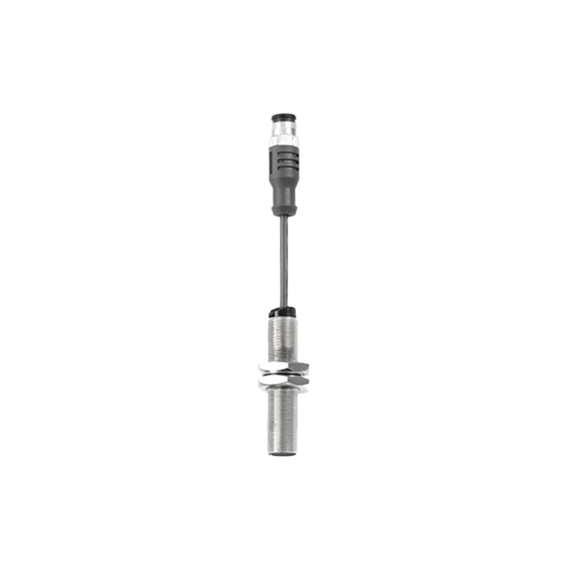
When reviewing a proximity sensor datasheet, several key parameters demand careful attention. The sensing distance, or nominal range, is the first consideration. It is crucial to note that this rated distance is typically defined for a standard mild steel target; factors like target material, size, and shape can significantly reduce the effective range. Repeat accuracy, the sensor's ability to consistently detect at the same point, is vital for precision applications. Response frequency indicates how quickly the sensor can detect objects passing by, measured in Hertz (Hz), which is critical for high-speed counting or sorting. Housing material, typically nickel-plated brass, stainless steel, or PBT plastic, determines environmental resilience. Finally, the protection class, denoted by IP or NEMA ratings, specifies defense against solids and liquids, ensuring reliable operation in washdown or outdoor conditions.
Inductive vs. Capacitive Sensor Types
The two most common proximity sensor technologies are inductive and capacitive, each suited for distinct materials. Inductive proximity sensors generate an electromagnetic field to detect metallic objects, primarily ferrous metals like steel and iron, though some models can sense non-ferrous metals like aluminum or copper at reduced ranges. They are ideal for position detection of machine parts, limit switching, and metal object counting. Capacitive proximity sensors, conversely, can detect nearly any material—metals, plastics, liquids, powders, and wood—by measuring changes in capacitance. This makes them perfect for applications like liquid level detection, non-metallic material handling, or seeing through thin container walls. The choice hinges entirely on the target material composition.
Output Configuration and Wiring Considerations
The electrical output of a proximity sensor defines how it communicates detection to the control system. The main configurations are NPN (sinking) and PNP (sourcing) for DC sensors, and AC two-wire or DC three-wire models. NPN outputs switch the negative (0V) line to the load, common in Asian-designed systems, while PNP outputs switch the positive voltage line, prevalent in European and North American designs. Selecting the wrong type for your PLC input module will result in incompatibility. Load current capacity, short-circuit and reverse polarity protection, and the presence of an output status LED are other vital wiring considerations. Always ensure the sensor's voltage range matches the available supply and that wiring is performed according to the manufacturer's diagram to prevent damage.
Application-Specific Selection Criteria
Moving beyond general specs, successful implementation requires matching the sensor to the application's unique demands. For high-speed automation, such as on a bottling line, a sensor with a very high response frequency and minimal hysteresis is necessary. In metal machining applications with heavy coolant spray, a sensor with a high IP rating (e.g., IP67 or IP69K) and a stainless-steel housing is mandatory. For detecting small parts, ensure the target is at least as large as the sensor's active face to guarantee reliable switching. In tight spaces, consider cylindrical "barrel" sensors or flat-pack rectangular designs. For challenging backgrounds, sensors with embedded background suppression or teach-in functionality can be programmed to ignore distant objects, focusing only on the desired detection zone.
Installation and Environmental Best Practices
Proper installation is critical to achieving the performance specified in the datasheet. Maintain the recommended gap between the sensor face and the target, known as the mounting distance, to avoid shock and vibration damage. For flush-mountable sensors, ensure they are recessed in metal to allow their shielded design to function correctly. Unshielded sensors offer longer ranges but require clearance from surrounding metal. Avoid mounting sensors directly opposite each other to prevent mutual interference; stagger them if multiple detection points are needed. Consider temperature extremes, which can affect sensing distance and electronics lifespan. In highly inductive load circuits (e.g., driving a relay coil), use a protective circuit like a flyback diode to suppress voltage spikes that could damage the sensor's output transistor