Understanding Common Sources of Interference
Photoelectric sensors are critical components in automation and control systems, prized for their non-contact detection and high precision. However, their reliable operation can be severely compromised by various forms of electrical and optical interference. A primary source is electromagnetic interference (EMI) from nearby high-power equipment such as variable frequency drives (VFDs), motors, solenoids, or welding machines. These devices generate transient voltage spikes and high-frequency noise that can couple onto sensor signal lines or power supplies, leading to false triggering or signal loss. Another significant category is optical interference, often referred to as "optical crosstalk." This occurs when the sensor's emitted light beam is inadvertently reflected from shiny surfaces, background objects, or even dust and vapor particles in the air, causing the receiver to detect a signal that does not correspond to the target's actual position. Ambient light, especially from high-intensity sources like sunlight or strobe lights, can also flood the receiver, saturating its photodiode and rendering it unable to distinguish its own modulated signal.
Implementing Robust Electrical Design Practices
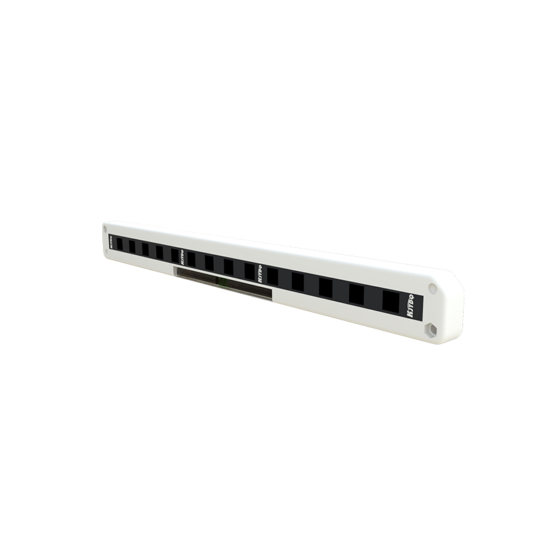
Mitigating electrical interference begins at the design and installation stage. Proper grounding is paramount; a single-point, low-impedance ground for the entire control system, including sensor housings and shields, is essential to create a common reference potential and divert noise away from sensitive circuits. The use of shielded cables for all sensor connections is highly recommended. The cable shield should be grounded at the controller end only to prevent ground loops. For sensors operating on DC power, incorporating filtering at the power supply input can suppress conducted noise. In environments with severe EMI, employing sensors with differential line-driver outputs (like RS-422) instead of standard voltage outputs provides superior common-mode noise rejection. Physically separating sensor cables from power lines, motor leads, and other potential noise sources is a simple yet effective rule. Maintain a minimum separation distance, and if cables must cross, ensure they do so at a 90-degree angle to minimize inductive coupling.
Optimizing Optical Configuration and Sensor Selection
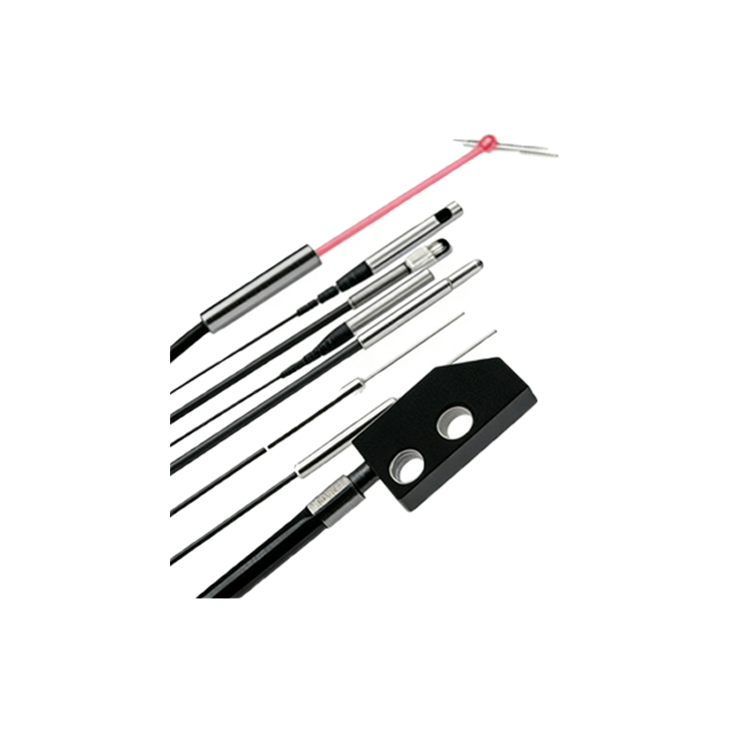
Addressing optical interference requires careful consideration of the sensor's operating principle and its environment. For diffuse reflective sensors, which detect light reflected directly from the target, issues with background reflection are common. Solutions include using sensors with background suppression technology, which employs triangulation to limit the sensing field to a specific distance, effectively ignoring objects beyond that point. Alternatively, retro-reflective sensors with polarizing filters can be used to ignore reflections from shiny targets, as the filter only allows light with a specific polarization to pass. For through-beam sensors, ensuring precise alignment is critical to avoid signal degradation. In dusty or foggy environments, selecting sensors with a modulated (pulsed) LED light source and a receiver tuned to that specific frequency allows the sensor to distinguish its signal from constant ambient light, dramatically improving stability. Adjusting the sensor's sensitivity setting to the minimum level required for reliable detection can also help reject weaker, spurious reflections.
Utilizing Advanced Features and Diagnostic Tools
Modern photoelectric sensors come equipped with sophisticated features designed to combat interference. Many models offer adjustable response time or "on/off delay" functions. By increasing the response time, the sensor's internal logic can be set to require the detected signal to be present for a minimum duration before changing state, effectively filtering out short-duration noise pulses. Synchronization (or mutual interference prevention) functions are vital when multiple sensors of the same type are installed in close proximity. This feature allows sensors to operate on alternating cycles, preventing one sensor's emitted light from being detected by a neighboring sensor's receiver. Furthermore, leveraging built-in diagnostic indicators, such as stable signal strength LEDs or IO-Link communication capabilities, provides invaluable real-time feedback. IO-Link, for instance, allows an engineer to monitor the received signal intensity, adjust parameters remotely, and set alarms for signal degradation, enabling proactive maintenance before a failure occurs.
Developing a Systematic Troubleshooting Protocol
When interference-related faults occur, a systematic approach is necessary for efficient resolution. Begin by verifying the symptom: is the sensor failing to detect a present object (false negative) or triggering without an object (false positive)? Isolate the sensor by temporarily powering down nearby high-noise machinery to see if the behavior changes. Check all physical connections, cable integrity, and grounding points for corrosion or looseness. Use an oscilloscope to inspect the sensor's output signal on the control input card for noise or instability. For optical issues, observe the environment for changes in ambient light, new reflective surfaces, or accumulation of contaminants on the lens. Temporarily adjusting the sensor's mounting angle or position can often confirm an optical crosstalk issue. Documenting the environment, sensor parameters, and any changes made is crucial for identifying patterns and implementing a permanent solution, which may involve sensor relocation, adding physical barriers (baffles), or upgrading to a more robust sensor model suited for the specific interference challenge.