Introduction to Photoelectric Sensor Alarm Systems
Photoelectric sensors are pivotal components in modern industrial automation, providing non-contact detection of objects, positions, or specific conditions. These sensors operate by emitting a beam of light—typically infrared, visible, or laser—and detecting changes in the received light signal caused by the presence or absence of a target. Their applications span across manufacturing lines, packaging systems, safety barriers, and material handling, where reliable detection is critical for operational efficiency and personnel safety. However, the sensor's detection signal alone is often insufficient for immediate human intervention, especially in noisy or visually complex environments. This necessity gives rise to integrated alarm circuits that translate sensor outputs into unmistakable audible and visual warnings. An effective alarm system ensures that any detected event, such as a fault, obstruction, or process deviation, is communicated promptly, enabling swift corrective actions and preventing potential downtime or hazards.
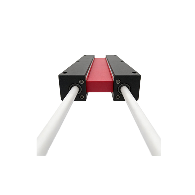
Core Components of the Alarm Circuit
The design of a photoelectric sensor alarm circuit revolves around several key electronic components that work in concert. At the heart lies the photoelectric sensor itself, which generates a digital or analog output signal based on its detection state. For alarm purposes, a digital output (e.g., NPN or PNP transistor switch) is commonly used, providing a clear high/low voltage signal indicating "detected" or "not detected." This signal is fed into a processing unit, which can be a simple transistor amplifier, an operational amplifier (op-amp) comparator circuit, or a programmable logic controller (PLC) in more complex setups. The processing unit conditions the sensor signal to drive the alarm indicators. For visual alerts, high-brightness LEDs or strobe lights are employed, often with distinct colors (red for critical alarms, amber for warnings). Audible alerts are generated by piezoelectric buzzers, sirens, or electronic beepers, which can produce varying tones or volumes. Power regulation components, such as voltage regulators and current-limiting resistors, ensure stable operation, while protective elements like diodes and fuses safeguard against voltage spikes or short circuits.
Circuit Design and Operational Principles
A typical alarm circuit begins with the photoelectric sensor's output connected to the base of an NPN bipolar junction transistor (BJT) or the gate of a MOSFET, acting as a switch. When the sensor detects an object, its output goes high (or low, depending on configuration), turning on the transistor. This allows current to flow from the power supply through the collector-emitter path, activating the alarm devices connected in series or parallel. For instance, a common design uses the transistor to energize a relay coil; the relay contacts then close to power a high-intensity LED and a buzzer simultaneously. To customize alarm behavior, additional logic can be incorporated. A 555 timer IC can be configured in astable mode to make the LED flash or the buzzer emit intermittent beeps, increasing attention-grabbing effectiveness. Diodes are placed across inductive loads (like relay coils) to suppress back-electromotive force (back-EMF) transients. The circuit's power supply is typically 12V or 24V DC, aligning with standard industrial control voltages. Resistor values are calculated based on the desired current for LEDs (using Ohm's Law) and the transistor's gain to ensure saturation.
Implementation and Wiring Considerations
Proper implementation of the alarm circuit requires careful attention to wiring and physical layout. Start by selecting a photoelectric sensor with an output type (sourcing or sinking) compatible with the alarm circuit's input. For example, an NPN (sinking) sensor output should interface with a circuit expecting a ground signal to trigger. Use shielded cables for sensor connections in electrically noisy environments to prevent electromagnetic interference (EMI) from causing false alarms. Keep power lines and signal lines separated to minimize cross-talk. When mounting visual indicators like LEDs, consider their viewing angle and ambient lighting conditions; opt for diffused lenses for wider visibility. Audible devices should be chosen based on the ambient noise level—a 85 dB buzzer may suffice in a quiet lab, but a 100+ dB siren is necessary for a factory floor. Incorporate a test button in the circuit to manually activate alarms for routine checks. All connections must be secure, using terminal blocks or soldered joints, and the entire assembly should be housed in an appropriate enclosure rated for the operational environment (e.g., IP65 for dust and water resistance). Label all wires and components clearly for maintenance.
Testing, Troubleshooting, and Maintenance
After assembly, systematic testing is crucial. First, verify the sensor's detection range and alignment using a target object; adjust sensitivity potentiometers if available. Use a multimeter to check voltage levels at key points: the sensor output, transistor base/collector, and alarm terminals. Ensure the alarm activates only when the sensor is triggered. If the alarm fails to sound or light, check for open circuits, blown fuses, or incorrect polarity. A stuck-on alarm might indicate a shorted transistor or sensor output. For intermittent operation, inspect for loose connections or power supply fluctuations. Regular maintenance includes cleaning sensor lenses to prevent false triggers from dust accumulation, testing alarm functionality weekly, and replacing any degraded components like buzzers with worn-out diaphragms. Log all tests and incidents to identify recurring issues. In programmable setups (using a PLC or microcontroller), monitor the logic to ensure alarm conditions are correctly mapped and that mute or acknowledge functions work as intended.
Advanced Features and Integration
Beyond basic alarms, advanced circuits can incorporate features for enhanced functionality. Integrating a microcontroller (e.g., Arduino, PIC) allows for programmable alarm patterns, delay timers, and communication protocols. For instance, the alarm can be programmed to sound only after a detection persists for over 5 seconds, ignoring transient interruptions. Serial communication (RS-485, Modbus) or industrial Ethernet enables the alarm status to be sent to a supervisory control and data acquisition (SCADA) system, providing remote monitoring and logging. Adding a memory latch circuit ensures the alarm remains active even if the sensor condition returns to normal, requiring a manual reset. Dual-level alarms can use two sensors or a single sensor with analog output to trigger different warnings for caution and critical states. Energy-efficient designs employ pulse-width modulation (PWM) to drive LEDs and buzzers, reducing power consumption. For safety-critical applications, redundancy can be built by using two independent sensor-alarm circuits in parallel. Always comply with relevant industry standards (e.g., IEC 60947, UL 508) for electrical safety and performance.
Conclusion and Best Practices
Designing and implementing a photoelectric sensor audible and visual alarm circuit is a straightforward yet vital task in industrial automation. The key to success lies in selecting appropriate components, following sound electrical design principles, and considering the operational environment. Always prioritize clarity and reliability—alarms must be unmistakable and fail-safe. Document the circuit design thoroughly, including schematics, parts lists, and calibration procedures. Train personnel on the alarm meanings and response protocols. As technology evolves, consider upgrading to smart sensors with built-in alarm outputs or wireless