Introduction to 5-Core Photoelectric Sensors
A 5-core photoelectric sensor is a versatile industrial device used for detecting objects, measuring distances, or monitoring processes through light-based technology. Unlike simpler 2-wire or 3-wire sensors, the 5-core configuration provides enhanced functionality, including separate lines for power supply, output signals, and auxiliary controls. These sensors are widely applied in automation systems, packaging machinery, and safety installations due to their reliability and precision. Understanding the wiring diagram is crucial for proper installation, ensuring optimal performance and preventing operational failures. This guide details the standard wiring practices, core functions, and common applications to assist engineers and technicians in implementing these sensors effectively.
Core Functions and Wire Identification
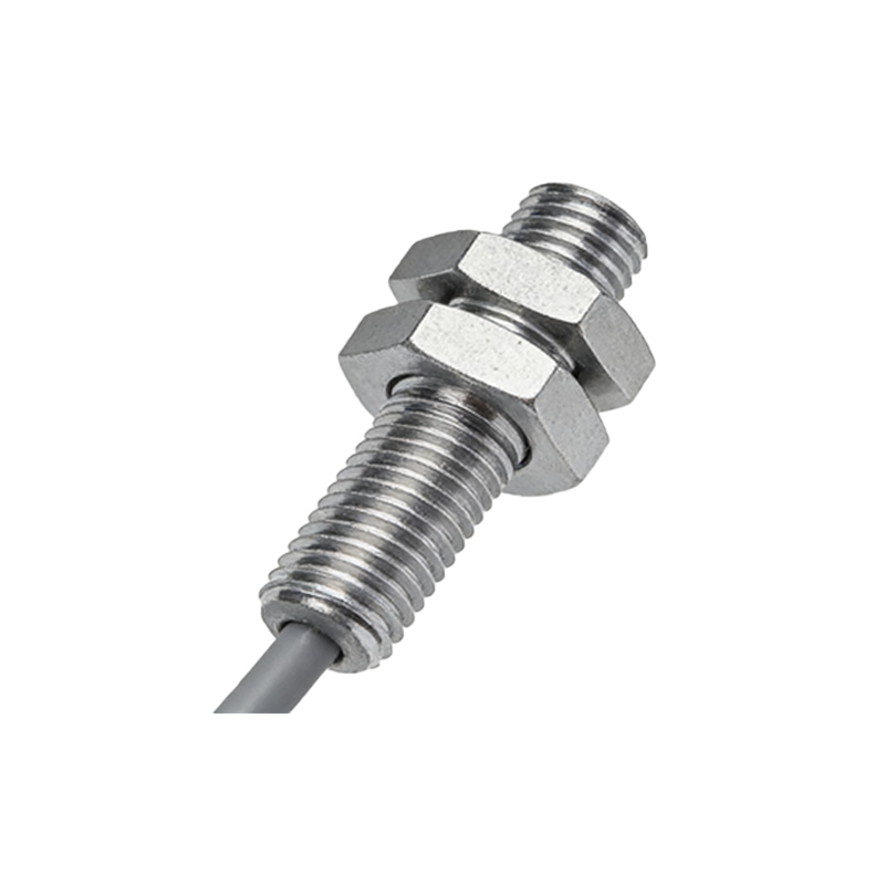
Each wire in a 5-core photoelectric sensor serves a specific purpose, typically color-coded for easy identification. The standard wiring includes: a brown wire for positive DC power supply (often +12V to +24V), a blue wire for negative DC power or ground (0V), a black wire for the output signal (normally open or normally closed), a white wire for an auxiliary output or control input, and a gray wire for complementary functions like timer settings or diagnostic feedback. It's essential to consult the manufacturer's datasheet, as color schemes may vary by brand. Proper identification ensures correct connections to power sources, controllers (e.g., PLCs), and other devices, minimizing risks of short circuits or sensor damage.
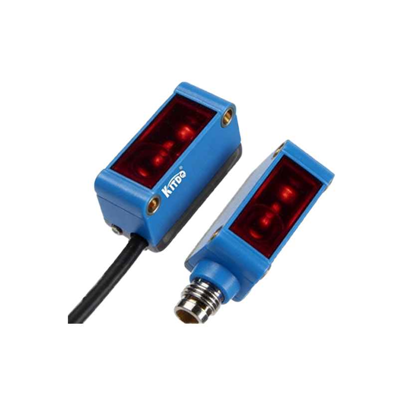
Standard Wiring Diagram Configuration
The wiring diagram for a 5-core photoelectric sensor typically follows a structured layout. Connect the brown wire to the positive terminal of the DC power supply and the blue wire to the negative terminal. The black output wire links to the input module of a controller, such as a PLC, to transmit detection signals. The white wire may be wired to an auxiliary device for additional control, like activating an alarm or relay. The gray wire often interfaces with programmable settings, allowing adjustments like sensitivity or delay times. Ensure all connections are secure and insulated, and use shielded cables in environments with electrical noise to prevent interference. A diagram example might show these connections in a ladder logic format for clarity in industrial setups.
Installation and Safety Considerations
During installation, prioritize safety by disconnecting power before wiring. Mount the sensor securely in a stable position, aligning the emitter and receiver for accurate detection. Avoid placing it near reflective surfaces or direct sunlight, which can cause false triggers. Check voltage ratings to match the power supply, typically within 10-30V DC, to prevent overheating or malfunction. Use conduit or cable glands for protection in harsh conditions like dust or moisture. Test the sensor after wiring by observing indicator LEDs and verifying output responses with a multimeter or controller monitor. Regular maintenance, such as cleaning lenses and inspecting connections, prolongs sensor life and ensures consistent operation.
Common Applications and Troubleshooting
5-core photoelectric sensors are employed in diverse scenarios, including object counting on conveyor belts, edge detection in printing machines, and safety barriers in robotic cells. Their multiple wires enable complex functions, like dual outputs for different processes or programmable logic integration. If issues arise, common troubleshooting steps involve checking power supply stability, verifying wiring against the diagram, and adjusting sensitivity settings. For instance, no output signal might indicate a loose black wire connection, while erratic behavior could stem from electrical noise—addressing this with proper grounding or filters often resolves it. Consulting the sensor manual for error codes or diagnostic modes can further aid in quick repairs.
Conclusion and Best Practices
In summary, correctly wiring a 5-core photoelectric sensor is key to leveraging its full capabilities in industrial automation. Always refer to the specific wiring diagram provided by the manufacturer, as variations exist across models. Adopt best practices like labeling wires, using quality connectors, and documenting installations for future reference. By following this guide, engineers can ensure reliable sensor performance, enhance system efficiency, and reduce downtime. As technology evolves, staying updated with new sensor features and wiring standards will continue to support advanced applications in smart manufacturing and IoT environments.