Understanding Proximity Sensor Function in Harvesters
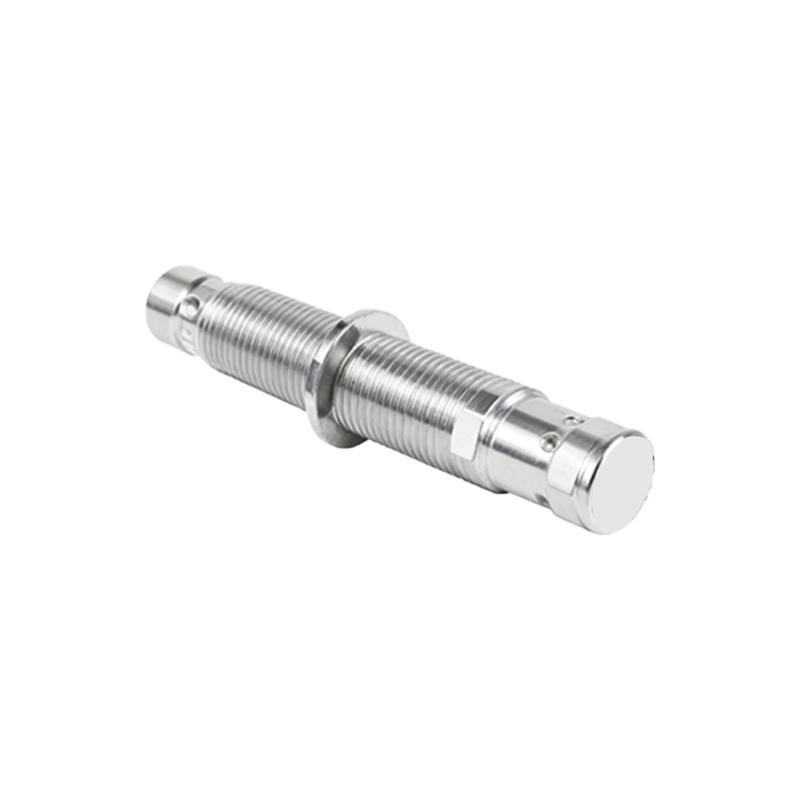
Proximity sensors are critical components in modern Lovol combine harvesters, serving as the electronic eyes for various automated systems. These non-contact sensors detect the presence or absence of metallic objects, such as rotating shafts, moving chains, or position markers, without physical interaction. In a harvesting context, they are commonly used for monitoring rotor speed, detecting grain tank levels, ensuring sieve positioning, and safeguarding drive components. The most prevalent type installed in Lovol machinery is the inductive proximity sensor, designed to reliably detect ferrous metals even in harsh, dusty environments. Proper installation is paramount, as incorrect mounting can lead to erratic machine behavior, false readings, or complete system failure, directly impacting harvesting efficiency and potentially causing costly downtime during critical seasons.
Pre-Installation Planning and Safety Protocols
Before handling any tools, a thorough planning phase is essential. Begin by consulting the specific Lovol combine harvester's technical manual and electrical schematic to identify the exact sensor model (e.g., LJ12A3-4-Z/BX) and its designated mounting location. Gather all necessary tools: appropriate wrenches, a multimeter for continuity and voltage checks, wire strippers, crimping tools, heat shrink tubing, and cable ties. Safety is non-negotiable. Ensure the harvester is completely powered down. Disconnect the negative terminal of the main battery to eliminate any risk of electrical shock or short circuits. Engage the parking brake and, if possible, lower the header to the ground to stabilize the machine. Work in a clean, well-lit area to avoid contaminating electrical connections with soil or chaff.
Selecting and Preparing the Mounting Location
Locate the precise mounting point as indicated in the manual. This is typically on a bracket near the component to be monitored, such as the rotor drive shaft or the grain elevator chain sprocket. The mounting surface must be solid, clean, and free from vibration as much as possible. Use a rag and electrical contact cleaner to remove all grease, dirt, and rust. For bracket-mounted sensors, ensure the bracket is securely fastened to the machine frame. The critical step is determining the correct sensing distance. Inductive sensors have a rated sensing range (e.g., 4mm). The target—like a bolt head on a rotating disk—must pass within this range. Use a feeler gauge to set a preliminary gap slightly less than the sensor's nominal range, typically 75-90% of it, to ensure a strong and reliable signal without risk of physical collision.
Mechanical Mounting and Alignment Procedures
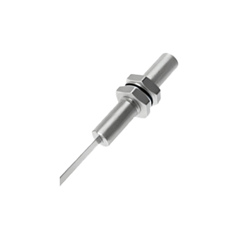
Secure the proximity sensor into its mounting nut or bracket. Do not overtighten, as this can damage the sensor housing or distort its sensing field. Follow the torque specifications if provided. The alignment of the sensor face relative to the target is crucial. The face should be parallel to the surface of the passing target. For a bolt head target on a rotating disk, the sensor should be aligned axially, pointing directly at the path of the bolt. Misalignment can drastically reduce the effective sensing range. After loosely tightening, manually rotate the target component (if accessible) to check for clearance throughout a full rotation. There must be no physical contact. Once alignment is confirmed, finalize the tightening of the mounting hardware, taking care not to shift the sensor's position.
Electrical Wiring and Connection Standards
Lovol harvesters typically use 3-wire DC sensors (Brown: +V, Blue: 0V/Common, Black: Signal Output). Route the sensor cable away from high-voltage lines, moving hydraulic hoses, and sharp edges. Use conduit or protective loom in high-wear areas and secure the cable with ties every 300mm. Strip and crimp insulated ring terminals to the wire ends. Connect the brown wire to the positive supply terminal (often +24V), the blue wire to the machine ground or negative terminal, and the black signal wire to the designated input on the harvester's controller or monitor. Ensure all connections are tight and corrosion-free. Apply heat shrink tubing over crimped connections for environmental sealing. Never splice sensor wires with simple twist connectors; always use proper waterproof connectors or terminal blocks.
Testing and Calibration for Optimal Performance
With wiring complete and double-checked, reconnect the battery. Power on the harvester's electrical system but do not start the engine. Use a multimeter to verify that the correct voltage is present at the sensor's power wires. The key test is to monitor the sensor's output. Set your multimeter to DC voltage and probe the black signal wire and ground. Bring a piece