In the world of industrial automation, the seamless integration of hardware and software is paramount. Programmable Logic Controllers (PLCs) serve as the brains of countless operations, from assembly lines to packaging systems. However, for a PLC to make intelligent decisions, it requires accurate data about its environment. This is where proximity sensors come into play. These non-contact detection devices are the eyes of the automation system, providing critical input to the PLC program. Understanding how to program a PLC to interface with these sensors is a fundamental skill for any automation engineer or technician.
Proximity sensors detect the presence or absence of an object without physical contact. They operate on various principles, primarily inductive, capacitive, and photoelectric. Inductive sensors are used for detecting metallic objects, capacitive sensors can detect both metallic and non-metallic materials, and photoelectric sensors use light beams. Each type sends a discrete signal—typically a simple ON (object detected) or OFF (no object detected)—to a designated input point on the PLC. This signal is represented internally as a single bit of data, either a 1 or a 0.
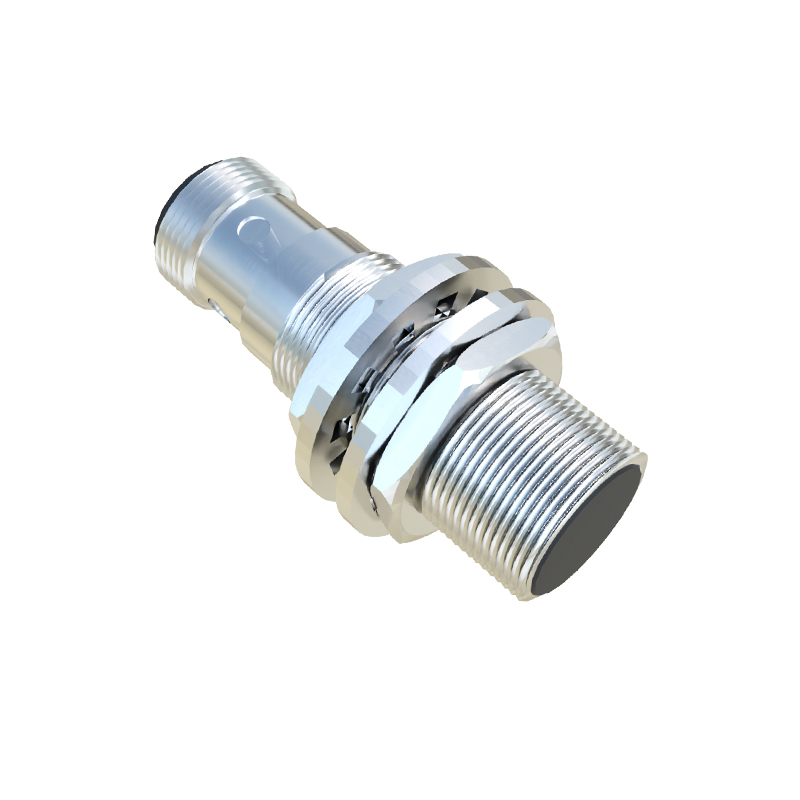
The first step in PLC programming for a proximity sensor is correct hardware configuration. This involves physically wiring the sensor to the PLC's input module. A standard three-wire DC sensor (brown wire for +24V DC, blue wire for 0V DC, and black wire for the signal output) is common. The sensor's output wire connects to a specific terminal on the input module, such as I0.0 or X1. This physical connection assigns a unique address to that sensor within the PLC's memory map. It is crucial to consult both the PLC and sensor datasheets for voltage, current, and wiring specifications to prevent damage.
Within the PLC programming software, the programmer then utilizes this input address as a condition in the control logic. Using ladder logic, the most common PLC programming language, the sensor's input is represented as a normally open (NO) or normally closed (NC) contact. For instance, if an inductive sensor (addressed as I0.1) is used to detect a metal part arriving at a workstation, its signal might be used to activate a timer, trigger a pneumatic cylinder via a PLC output, or increment a counter.
Consider a basic example: a conveyor system where a photoelectric sensor detects a box. When the box breaks the sensor's light beam, input I0.2 becomes TRUE (1). In the ladder logic rung, this condition can be programmed to energize an output coil, say Q0.5, which stops the conveyor motor. A timer instruction (TON) might then be activated to create a dwell period before the next process begins. The logic is direct: IF Sensor_I0.2 is ON, THEN activate Output_Q0.5 and Start Timer_T37.
Beyond simple detection, advanced programming techniques enhance functionality. Sensors can be used for precise positioning, jam detection, or part counting. For counting, a counter instruction (CTU) is incremented each time the sensor's signal transitions from OFF to ON. Debouncing logic, often using timers, may be necessary to filter out mechanical vibration or electrical noise that could cause false triggers, ensuring count accuracy. For safety interlocks, multiple sensor inputs can be combined in series (AND logic) or parallel (OR logic) to create permissive conditions for machine operation.
Troubleshooting is a critical aspect. A programmer must be able to differentiate between a sensor failure, a wiring fault, and a logic error. Most modern PLC software includes online monitoring features, allowing the programmer to see the real-time status of each input bit. If a sensor is physically detecting an object but the corresponding input bit remains FALSE, the issue likely lies in the wiring, power supply, or the sensor itself. Conversely, if the input is TRUE without an object present, it could indicate a stuck sensor or a short circuit.
In practice, successful implementation requires careful sensor selection—considering factors like sensing range, material composition of the target, and environmental conditions (e.g., washdown, temperature)—followed by meticulous programming that translates simple binary signals into robust and reliable machine control. The synergy between the durable, field-level sensor and the flexible, logic-driven PLC creates the responsive and automated systems that drive modern manufacturing. Mastery of this interface is not just about writing code; it's about designing a reliable flow of information from the physical world into the digital control system, enabling precise, efficient, and safe automation.