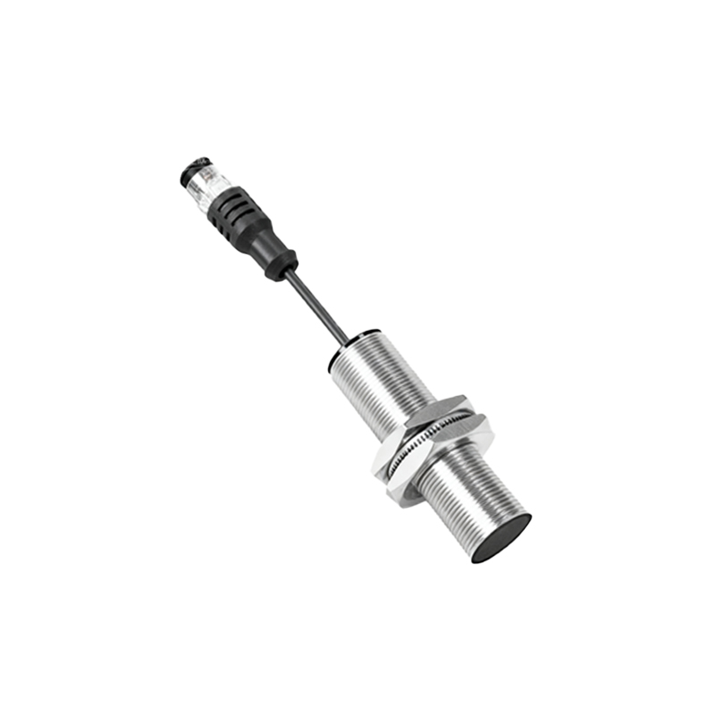
In the realm of industrial automation and machinery design, proximity sensors are indispensable components. They detect the presence or absence of an object without physical contact, enabling critical functions like position verification, counting, and safety interlocks. For engineers and designers using SolidWorks, integrating these sensors into digital prototypes is a fundamental step toward creating efficient and reliable automated systems. This guide delves into the practical aspects of working with proximity sensors within the SolidWorks ecosystem, covering selection, modeling, and simulation.
Understanding the types of proximity sensors is the first step toward accurate modeling. The most common variants include inductive, capacitive, and photoelectric sensors. Inductive sensors detect metallic objects and are ideal for harsh industrial environments. Capacitive sensors can detect both metallic and non-metallic materials, including liquids and powders. Photoelectric sensors use light beams to detect objects at greater distances. When designing in SolidWorks, knowing the sensor type influences the surrounding geometry, material assignments, and eventual placement in the assembly. For instance, the sensing face of an inductive sensor requires clearance from metallic mounting brackets to avoid false triggers—a detail that must be accounted for in the 3D model.
SolidWorks provides robust tools for incorporating sensor components. Engineers typically begin by downloading a precise 3D model of the sensor from the manufacturer's website or a certified parts library like SolidWorks Toolbox or 3DContentCentral. These models often include detailed external geometry and accurate mounting features. It is crucial to use these certified models to ensure the dimensional accuracy of mounting holes, connector positions, and overall envelope size. Simply extruding a basic cylinder to represent a sensor can lead to fit and interference issues downstream. Once placed in the assembly, mates are used to position the sensor correctly relative to the target object. Defining the sensor's effective sensing range and field of view as reference geometry or sketches can visually communicate its operational zone to other team members.
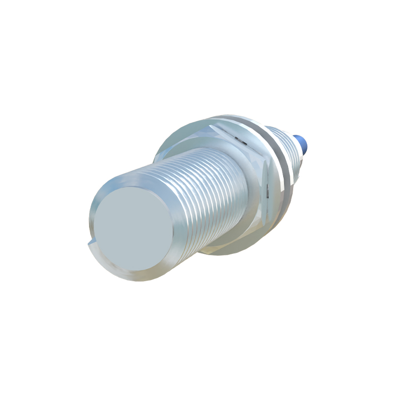
Beyond static placement, SolidWorks Simulation and SOLIDWORKS Electrical offer pathways for more advanced integration. While a standard CAD model represents the physical housing, SOLIDWORKS Electrical allows for the intelligent integration of the sensor as an electrical component. This involves linking the 3D model to a symbol in the schematic, defining its electrical characteristics, and routing wires to its connection points. This bidirectional association ensures that any change in the schematic updates the 3D assembly and vice versa, maintaining design integrity. For motion analysis, sensors can be used in conjunction with SolidWorks Motion. Although the software doesn't simulate the electrical signal output directly, you can set up sensor entities within Motion studies to monitor specific events. For example, you can define a proximity sensor to trigger an action (like stopping a motor) when the distance between the sensor's origin and a face on the target part falls below a set threshold. This enables functional validation of mechanisms like automated gates or pick-and-place arms before physical prototyping.
Effective design with proximity sensors in SolidWorks also hinges on best practices for documentation and collaboration. Annotating the 2D drawing with clear callouts for the sensor's part number, sensing range, and required supply voltage is essential for manufacturing and procurement. Utilizing configurations can manage different sensor models within the same assembly footprint. For complex systems, the Interference Detection tool should be run not just for physical clashes, but also to ensure the sensor's "field of view" is not obstructed by other components. This virtual verification prevents costly errors where a sensor is physically mounted but cannot "see" its target due to an unexpected bracket or conduit.
Ultimately, treating proximity sensors as intelligent, functional components rather than mere 3D blocks elevates the design process. By leveraging detailed manufacturer models, utilizing electrical and motion simulation tools, and adhering to meticulous documentation practices, engineers can create digital prototypes in SolidWorks that closely mirror real-world behavior. This approach reduces prototyping cycles, minimizes installation errors, and contributes to the development of smarter, more responsive automated machinery. The goal is to move beyond shape and fit, toward a fully validated functional digital twin where the interaction between the sensor and its environment is predictable and reliable.